[nextpage title=”Introduction”]
Paxpower 500 W (also known as Powerpax 500 W or AK-P050FG7) is a mainstream power supply from Akasa, featuring active PFC and a 120 mm fan. Since this was the first product we’ve reviewed from this brand, we were very curious to see if it could really deliver its labeled power. Read on.
All power supplies from Akasa are manufactured by Enhance Electronics. This is the same factory behind Cooler Master Real Power Pro series, Antec TruePower Quattro series and newer power supplies from BFG. Keep in mind that not all models from these brands are manufactured by Enhance.
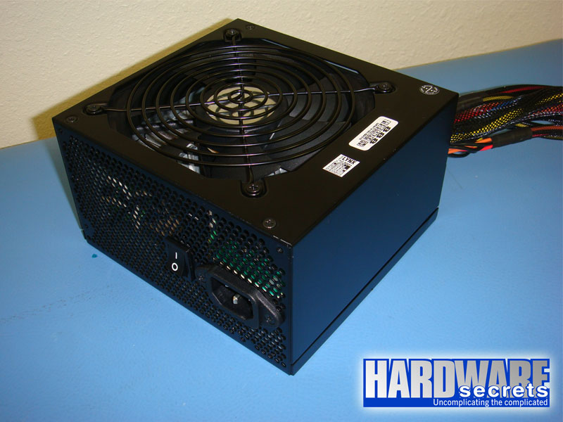 Figure 1: Akasa Paxpower 500 W power supply.
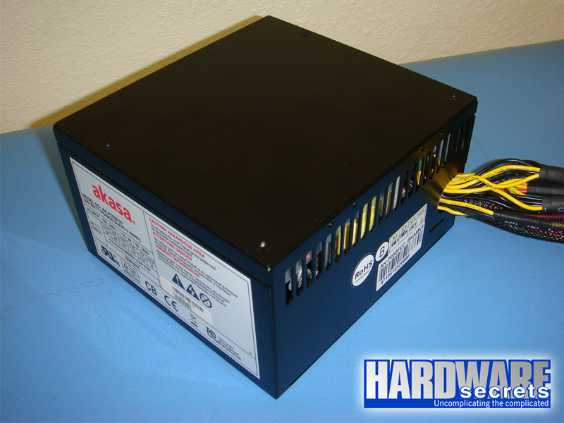 Figure 2: Akasa Paxpower 500 W power supply.
Akasa Paxpower 500 W is a small power supply (5 ½” or 14 cm deep).
All cables use a nylon protection, however only the protection used on the main motherboard cable comes from inside the power supply housing, as you can see in Figure 2.
The main motherboard cable uses a 20/24-pin connector and this unit comes with two ATX12V connectors that together form one EPS12V connector.
The reviewed power supply comes with five peripheral cables: one with one six-pin auxiliary power connector and one six/eight-pin auxiliary power connector for video cards, two with three SATA power connectors, one with three standard peripheral power plugs and one with three standard peripheral power plugs and one floppy disk drive power connector.
All wires are 18 AWG, which is the correct gauge to be used.
Even though this power supply presents a very good number of connectors – especially the presence of six SATA connectors on two separated cables, easily allowing you to install SATA hard disk drives and SATA optical drives – the two video card auxiliary power connectors are installed on the same cable. We prefer to see these connectors using independent cables, as the use of two connectors on the same cable tends to make voltage to drop on them when the power supply is fully loaded. Also there is only 5 29/32” (15 cm) between them, which can make it hard for you to install two video cards under SLI or CrossFire mode depending on your configuration.
The distance between the power supply housing and the first connector on each cable is of 20 5/64” (51 cm) – long cables, which is good – and the distance between each connector on cables that have more than one plug is of 5 29/32” (15 cm).
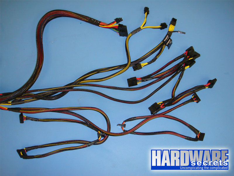 Figure 3: Cables.
Now let’s take an in-depth look inside this power supply.
[nextpage title=”A Look Inside The Paxpower 500 W”]
We decided to disassemble this power supply to see what it looks like inside, how it is designed, and what components are used. Please read our Anatomy of Switching Power Supplies tutorial to understand how a power supply works and to compare this power supply to others.
This page will be an overview, and then in the following pages we will discuss in detail the quality and ratings of the components used.
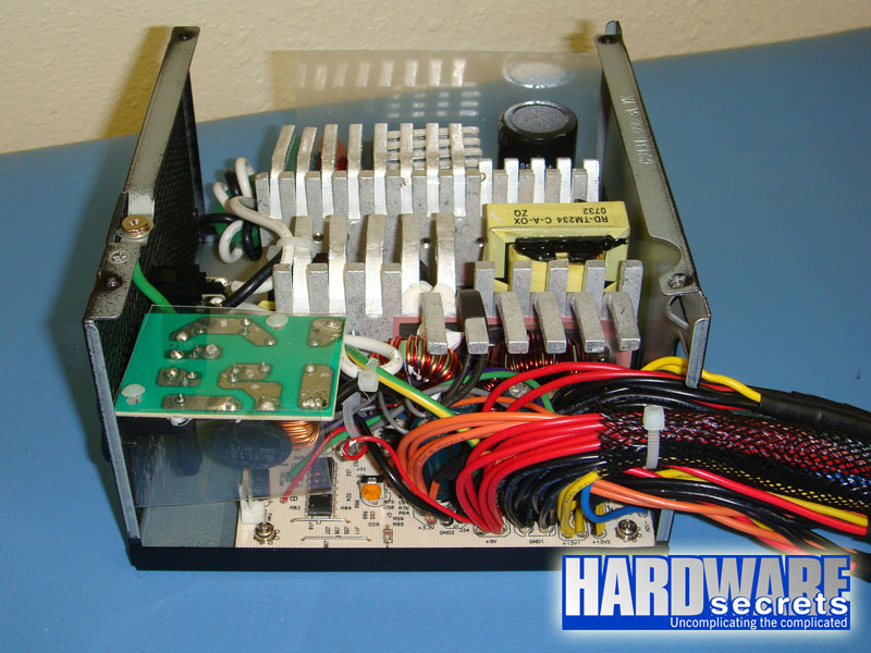 Figure 4: Overall look.
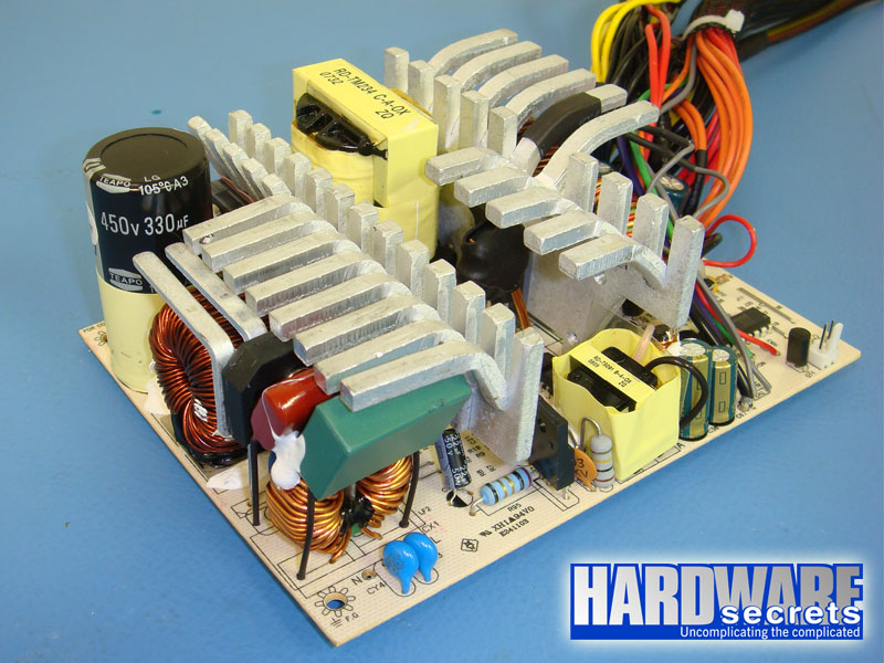 Figure 5: Overall look.
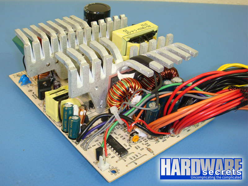 Figure 6: Overall look.
[nextpage title=”Transient Filtering Stage”]
As we have mentioned in other articles and reviews, the first place we look when opening a power supply for a hint about its quality, is its filtering stage. The recommended components for this stage are two ferrite coils, two ceramic capacitors (Y capacitors, usually blue), one metalized polyester capacitor (X capacitor), and one MOV (Metal-Oxide Varistor). Very low-end power supplies use fewer components, usually removing the MOV and the first coil.
This stage is excellent, with one X capacitor and two Y capacitors more than needed.
 Figure 7: Transient filtering stage (part 1).
 Figure 8: Transient filtering stage (part 2).
In the next page we will have a more detailed discussion about the components used in the Akasa Paxpower 500 W.
[nextpage title=”Primary Analysis”]
On this page we will take an in-depth look at the primary stage of Akasa Paxpower 500 W. For a better understanding, please read our Anatomy of Switching Power Supplies tutorial.
This power supply uses one KBU1005 rectifying bridge in its primary, which can deliver up to 10 A at 55° C. This component is clearly overspec’ed: at 115 V this unit would be able to pull up to 1,150 W from the power grid; assuming 80% efficiency, the bridge would allow this unit to deliver up to 920 W without burning this component. Of course we are only talking about this component and the real limit will depend on all other components from the power supply.
 Figure 9: Rectifying bridge.
On the active PFC circuit two STW20NK50Z power MOSFET transistors are used, each one capable of delivering up to 17 A at 25° C or 10.71 A at 100° C in continuous mode (note the difference temperature makes) or 68 A in pulse mode at 25&de
g; C.
The active PFC capacitor is from Teapo and labeled at 105° C. Usually manufacturers use 85° C capacitors here, so it is good to see a manufacturer using a capacitor with a higher temperature rating.
In the switching section, two STW14NK50Z power MOSFET transistors are used on the traditional two-transistor forward configuration. Each one is capable of delivering up to 14 A at 25° C or 7.6 A at 100° C in continuous mode (note the difference temperature makes) or 48 A in pulse mode at 25° C.
 Figure 10: One of the switching transistors, active PFC diode and active PFC transistors.
The primary is controlled by the omnipresent CM6800 PFC/PWM combo controller.
 Figure 11: PFC/PWM combo controller.
Now let’s take a look at the secondary of this power supply.
[nextpage title=”Secondary Analysis”]
This power supply uses five Schottky rectifiers on its secondary.
The maximum theoretical current each line can deliver is given by the formula I / (1 – D), where D is the duty cycle used and I is the maximum current supported by the rectifying diode. Just as an exercise, we can assume a typical duty cycle of 30%.
The +12 V output is produced by two rectifiers, however they are not connected in parallel. One FYPF2010DN has its two internal diodes connected in parallel and is in charge of the rectification (20 A at 105° C, i.e., 10 A per internal diode), while one STPS30H100CW has its two diodes connected in parallel and is in charge of the “freewheeling” portion of the rectification (i.e., discharging the coil). This device has a maximum current limit of 30 A (15 A per diode at 155° C). For our math we have to consider the part with the lower current limit, 20 A in our case. Applying the above formula gives us a maximum theoretical current of 29 A or 343 W for the +12 V output.
The +5 V output is produced by two STPS30L40CW Schottky rectifiers, each one capable of delivering up to 30 A (15 A per internal diode at 135° C). This means the +5 V output has a maximum theoretical current of 43 A or 214 W.
The +3.3 V output is produced by one MBR6045PT Schottky rectifier, which is capable of delivering up to 60 A (30 A per diode at 125° C), giving us a maximum theoretical current of 43 A or 141 W for the +3.3 V output.
 Figure 12: +3.3 V, +5 V and the two +12 V rectifiers. The other +5 V rectifier is on the other side from the heatsink.
This power supply uses a WT7517 monitoring integrated circuit, which is in charge of the power supply protections. It supports over voltage (OVP), under voltage (UVP) and over current (OCP) protections. OCP was really activated, as we will talk about later.
 Figure 13: Monitoring integrated circuit.
The electrolytic capacitors from the secondary are also from Teapo, with some models from Su’scon (both Taiwanese).
[nextpage title=”Power Distribution”]
In Figure 14, you can see the power supply label containing all the power specs.
 Figure 14: Power supply label.
As you can see this power supply has two +12 V rails, which are distributed like this:
- +12V1 (solid yellow wire): All cables but one of the ATX12V connectors.
- +12V2 (yellow with black stripe wire): One of the ATX12V connectors.
This distribution is really strange. Both ATX12V connectors should be connected to the second rail, but only one of them are. This showed to be a problem during our tests, as we will explain in the next page.
Now let’s see if this power supply can really deliver 500 W.[nextpage title=”Load Tests”]
We conducted several tests with this power supply, as described in the article Hardware Secrets Power Supply Test Methodology.
First we tested this power supply with five different load patterns, trying to pull around 20%, 40%, 60%, 80%, and 100% of its labeled maximum capacity (actual percentage used listed under “% Max Load”), watching how the reviewed unit behaved under each load. In the table below we list the load patterns we used and the results for each load.
If you add all the power listed for each test, you may find a different value than what is posted under “Total” below. Since each output can vary slightly (e.g., the +5 V output working at +5.10 V), the actual total amount of power being delivered is slightly different than the calculated value. On the “Total” row we are using the real amount of power being delivered, as measured by our load tester.
+12V1 and +12V2 are the two independent +12V inputs from our load tester and during our tests the +12V1 input was connected to the power supply +12V1 (main motherboard connector and peripheral power connectors) while the +12V2 input was connected to the power supply +12V1 and +12V2 rails (EPS12V connector), except on test number five, where we had to remove the ATX12V connector that was connected to +12V1 from the +12V2 input from our load tester, as we will explain below.
| Input | Test 1 | Test 2 | Test 3 | Test 4 | Test 5 |
| +12V1 | 4 A (48 W) | 7 A (84 W) | 11 A (132 W) | 14.5 A (174 W) | 18 A (216 W) |
| +12V2 | 3 A (36 W) | 7 A (84 W) | 10 A (120 W) | 14 A (168 W) | 18 A (216 W) |
| +5V | 1 A (5 W) | 2 A (10 W) | 4 A (20 W) | 5 A (25 W) | 6 A (30 W) |
| +3.3 V | 1 A (3.3 W) | 2 A (6.6 W) | 4 A (13.2 W) | 5 A (16.5 W) | 6 A (19.8 W) |
| +5VSB | 1 A (5 W) | 1 A (5 W) | 1.5 A (7.5 W) | 2 A (10 W) | 2.5 A (12.5 W) |
| -12 V | 0.5 A (6 W) | 0.5 A (6 W) | 0.5 A (6 W) | 0.5 A (6 W) | 0.5 A (6 W) |
| Total | 101.9 W | 192.6 W | 294.4 W | 391.4 W | 484.6 W |
| % Max Load | 20.4% | 38.5% | 58.9% | 78.3% | 96.9% |
| Room Temp. | 46.6° C | 46.3° C | 46.6° C | 46.7° C | 46.6° C |
| PSU Temp. | 49.8° C | 49.3° C | 50.2° C | 50.4° C | 51.6° C |
| Voltage Stability | Pass | Pass | Pass | Pass | Pass |
| Ripple and Noise | Pass | Pass | Pass | Pass | Pass |
| AC Power (1) | 122 W | 226 W | 351 W | 474 W | 612 W |
| Efficiency (1) | 83.5% | 85.2% | 83.9% | 82.6% | 79.2% |
| AC Power (2) | 129 W | 238 W | 367 W | 497 W | 636 W |
| Efficiency (2) | 78.7% | 81.0% | 80.3% | 78.7% | 76.2% |
| AC Voltage | 113.6 V | 112.1 V | 111.6 V | 110.4 V | 108.7 V |
| Power Factor | 0.958 | 0.986 | 0.994 | 0.996 | 0.997 |
| Final Result | Pass | Pass | Pass | Pass | Pass |
Updated 06/24/2009: We re-tested this power supply using our new GWInstek GPM-8212 power meter, which is a precision instrument and provides accuracy of 0.2% and thus presenting the correct readings for AC power and efficiency (results marked as “2” on the table above; results marked as “1” were measured with our previous power meter from Brand Electronics, which isn’t so precise as you can see). We also added the numbers for AC voltage during our tests, an important number as efficiency is directly proportional to AC voltage (the higher AC voltage is, the higher efficiency is). Also, manufacturers usually announce efficiency at 230 V, which usually inflates efficiency numbers. We added power factor (PF) numbers as well. These numbers measure the efficiency of the power supply active PFC circuit. This number should be as close to 1 as possible. Under light load (20% load, i.e., 100 W), the active PFC circuit from this unit isn’t as good as when operating under higher loads.
Efficiency was above 80% only when we pulled between 40% and 60% from this power supply labeled power (between 200 W and 300 W). On all other load patterns efficiency was below 80%.
Another problem we had with Akasa Paxpower 500 W was during test five: using the two ATX12V connectors at the same time connected to the load tester’s +12V2 input the power supply wouldn’t turn on. By removing the plug that was connected to the power supply’s +12V1 rail from the machine, the unit would turn on.
Ripple and noise was the highlight from this product, very low levels all the time. Below you see the waveforms during test number five. Just to remember, the maximum allowed is 120 mV at +12 V and 50 mV at +5 V and +3.3 V. All values are peak-to-peak.
 Figure 15: +12V1 rail with power supply delivering 484.6 W (36.4 mV).
 Figure 16: +12V2 rail with power supply delivering 484.6 W (35.4 mV).
 Figure 17: +5V rail with power supply delivering 484.6 W (14.4 mV).
 Figure 18: +3.3 V rail with power supply delivering 484.6 W (13.2 mV).
Now let’s see if we could pull more than 500 W from this unit.
[nextpage title=”Overload Tests”]
Before overloading power supplies we always test first if the over current protection (OCP) circuit is active and at what level it is configured.
In order to do that we configured our load tester with a low (1 A) current on +12V2 and increased current at +12V1 until the power supply shut down. This happened when we tried to pull more than 22.5 A from +12V1.
Manufacturers always leave a margin between what is written on the label (18 A in this case) and the level the OCP circuit is really configured (22.5 A in this case). We always like to see this margin as tight as possible.
Then starting from test five we increased currents to the maximum we could with the power supply still running inside ATX specs. The results are below. When we tried to increase one more amp at any output ripple would go to the roof, meaning that the unit stopped working correctly.
| Input | Maximum |
| +12V1 | 22.5 A (270 W) |
| +12V2 | 22.5 A (270 W) |
| +5V | 9 A (47.5 W) |
| +3.3 V | 7 A (23.1 W) |
| +5VSB | 4 A (20 W) |
| -12 V | 1.5 A (18 W) |
| Total | 624 W |
| % Max Load | 124.8% |
| Room Temp. | 46.6° C |
| PSU Temp. | 51.6° C |
| AC Power (1) | 834 W |
| Efficiency (1) | 74.8% |
| AC Power (2) | 881 W |
| Efficiency (2) | 70.8% |
| AC Voltage | 106.6 V |
| Power Factor | 0.995 |
Consider the results marked as “2”, as they are the correct ones, measured with our precision power meter.
[nextpage title=”Main Specifications”]
Akasa Paxpower 500 W (AK-P050FG7) power supply specs include:
- ATX12V 2.2
- Nominal labeled power: 500 W.
- Measured maximum power: 624 W at 46.6° C.
- Labeled efficiency: N/A
- Measured efficiency: Between 76.2% and 81.0% at 115 V (nominal, see complete results for actual voltage).
- Active PFC: Yes.
- Modular Cabling System: No.
- Motherboard Power Connectors: One 24-pin connector and two ATX12V connectors that together form an EPS12V connector.
- Video Card Power Connectors: One six-pin connector and one six/eight-pin connector, installed on the same cable.
- Peripheral Power Connectors: Six in two cables.
- Floppy Disk Drive Power Connectors: One.
- SATA Power Connectors: Six in two cables.
- Protections: N/A. The monitoring integrated circuit supports over current (OCP, tested and working), over voltage (OVP, not tested) and under voltage (UVP, not tested) protections. Short-circuit protection (SCP) present and working.
- Warranty: N/A.
- More Information: https://www.akasa.com.tw
- Real Manufacturer: Enhance Electronics
- Average price in the US: We couldn’t find the rev
iewed product being sold in the US.
[nextpage title=”Conclusions”]
We were very curious to test a power supply from Akasa, since we’ve never tested anything from them before.
We retested this product on 06/24/2009 with our new precision wattmeter and efficiency showed to be above 80% only if you pull between 200 W and 300 W from this power supply; with any other load efficiency was below 80%. Because of that we had to reconsider the award we gave to this product and we decided to downgrade this power supply to the “not recommended” status.
Also we could only extract 500 W from it after we removed the second ATX12V connector from the +12V2 input from our load tester. With both connectors installed there – i.e., using the EPS12V connector – the power supply wouldn’t turn on. Another thing we didn’t like about this unit was the fact that the two video card power connectors are located on the same cable instead of using separated cables.
On the good side Akasa Paxpower 500 W got very low noise and ripple levels. The length of the cables is good and it presents two cables with three SATA power connectors each, for a total of six SATA power connectors.
Although Akasa Paxpower 500 W (AK-P050FG7) can really deliver its labeled power, power isn’t everything and you should look for a product with better efficiency.
Leave a Reply