[nextpage title=”Introduction”]
The new Signature Series from Antec is a premium power supply line, which means that products from this series (so far 650 W and 850 W models were launched) have tighter specs. For example, voltage regulation is set at 3% instead of 5% (7% instead of 10% for the -12 V output). Between the lines the manufacturer says this line has a very high efficiency, although on the specs table they list efficiency as “80% minimum.” Signature 650, also known as SG-650, features a half modular cabling system and only one 80 mm fan, which the manufacturer says is quieter than other 80 mm solutions. Let’s see what is really inside this power supply and why it is so much more expensive than other units.
Of course this power supply features active PFC, what enables Antec to sell this product in Europe. Because of that it also has auto voltage selection.
Signature 650 comes in a fancy hard box, as you can see in Figure 1.

Figure 1: Antec Signature 650 box.

Figure 2: Antec Signature 650.
This power supply is a bigger than other products on the same power range, being 7 3/32” (180 mm) deep instead of 6 19/64” (160 mm) or even 5 ½” (140 mm).
As mentioned, this product has only one 80 mm fan on its rear side, just like older power supplies. We like better when power supplies have a 120 mm or bigger fan on its bottom as bigger fans provide higher airflow (meaning lower temperature) and lower noise level (as they can rotate at lower speeds to achieve the same airflow level of smaller fans). Antec, however, says that the fan used is quieter than normal, as it uses a PWM (Pulse Width Modulation) circuit to control it. In fact this proved to be true. During our reviews we could only hear the fan working when the power supply was delivering its full labeled power or more. The power supply worked very cool as well (only up to 5° C above room temperature), as we will show you in more details later.
But what is somewhat strange about this power supply is the fact that it uses a “half” modular cabling system, to be used only if you need more cables. Signature 650 comes with the main motherboard cable, ATX12V cable, EPS12V cable, SATA power cable (with three connectors), peripheral power cable (with three standard connectors and one floppy disk drive power connector) and video card cable (6/8-pin connector) coming from inside the power supply. Then it has three connectors on its modular cabling system if you need more peripheral, SATA or video card power cables.
It comes with two SATA power cables (three SATA power plugs each), two peripheral power cables (three standard peripheral power plugs each) and one video card power cable (one 6-pin plug). If you pay attention, the power supply comes with five extra cables, but its modular cabling system has only three connectors, so you can only use three of them at the same time (one of the connectors is reserved for the additional video card power connector).

Figure 3: Antec Signature 650.

Figure 4: Cables for the modular system.
All wires are 18 AWG, which is adequate for a power supply on this power range.
On the aesthetical side all cables use a nylon sleeving, but they don’t come from inside the power supply, so the wires are exposed on the hole on the front side of the power supply.
This power supply is manufactured by Delta Electronics.
Now let’s take an in-depth look inside this power supply.
[nextpage title=”A Look Inside The Signature 650″]
We decided to disassemble this power supply to see what it looks like inside, how it is designed, and what components are used. Please read our Anatomy of Switching Power Supplies tutorial to understand how a power supply works and to compare this power supply to others.
Disassembling Signature 650 it was clear why Antec decided to use an 80 mm fan instead of a bigger one: this power supply has two printed circuit boards. The upper board has its component side facing the component side of the lower board, so we have all components located in the middle with a lot of space for the airflow provided by the 80 mm fan. We could see that this fan is really a PWM model, since it had four wires and not only two as usual.
This is the second power supply we’ve seen with this kind of design. The first one was OCZ ProXStream 1,000 W, which proved to have very noisy and inefficient fans (they aren’t PWM) and to heat a lot. This model from OCZ, however, is physically smaller, which made all components to be squeezed in a very small space causing the excessive heating. This does not appear to be the case with Signature 650, where the components are well spread and there is a lot of empty space between the two printed circuit boards when the unit is assembled.
The top printed circuit board features part of the primary (transient filtering stage and active PFC) and the entire +5VSB power supply and the bottom printed circuit board features part of the primary (switching and transformer) and the whole secondary.

Figure 5: Overall look.

Figure 6: Upper printed circuit board.

Figure 7: Upper printed circuit board.

Figure 8: Lower printed circuit board.

Figure 9: Lower printed circuit board.
[nextpage title=”Transient Filtering Stage”]
As we have mentioned in ot
her articles and reviews, the first place we look when opening a power supply for a hint about its quality, is its filtering stage. The recommended components for this stage are two ferrite coils, two ceramic capacitors (Y capacitors, usually blue), one metalized polyester capacitor and one MOV (Metal-Oxide Varistor). Very low-end power supplies use fewer components, usually removing the MOV and the first coil.
This power supply is flawless on this stage, having one more ferrite coil, two more Y capacitors (two of them are soldered directly to the main AC connector) and two more X capacitors than necessary.
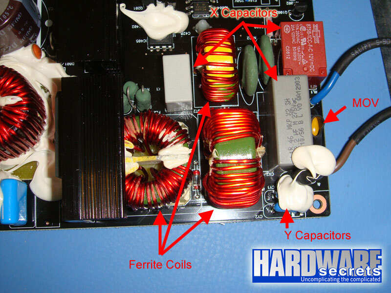
Figure 10: Transient filtering stage.
In the next page we will have a more detailed discussion about the components used in the Signature 650.
[nextpage title=”Primary Analysis”]
On this page we will take an in-depth look at the primary stage of Signature 650. For a better understanding, please read our Anatomy of Switching Power Supplies tutorial.
This power supply uses one D25XB60 rectifying bridge in its primary, capable of delivering up to 25 A at 95° C when a heatsink is used, which is the case. This bridge has a very high current limit, as bridges usually used on PC power supplies have a limit between 6 A and 15 A. This component is clearly overspec’ed: at 115 V this unit would be able to pull up to 2,875 W from the power grid; assuming 80% efficiency, the bridge would allow this unit to deliver up to 2,300 W without burning this component. Of course we are only talking about this component and the real limit will depend on all other components from the power supply.
The active PFC circuit uses two 20N60C3 power MOSFET transistors, which are probably the most popular transistors for this function. Each one is capable of handling up to 300 A @ 25° C in pulse mode (which is the case) or up to 45 A @ 25° C or 20 A @ 110° C (note the difference temperature makes).
The active PFC circuit uses two Japanese capacitors labeled at 105° C connected in parallel, one from Rubycon and the other from Chemi-Con. When capacitors are connected in parallel their capacitances are added. This is a very common trick to achieve a higher capacitance without using a capacitor that is physically bigger and would not fit the form factor proposed by the manufacturer. The capacitors are from different vendors because they are not identical, the Rubycon one is of 270 µF and the Chemi-Con one is of 220 µF. Thus together they are equivalent to a bigger 490 µF cap.

Figure 11: Active PFC circuit and rectifying bridge (component on the right).
While the transient filtering stage, the rectifying bridge and the active PFC circuit are located on the upper printed circuit board (along with the +5VSB power supply) the switching transistors and the transformer are located on the lower printed circuit board.
This power supply uses two other 20N60C3 power MOSFET transistors on the traditional two-transistor forward configuration on its switching section. The specs for these transistors are published above.

Figure 12: Switching transistors and transformer.
Since the active PFC circuit and the switching transistors are located in different printed circuit boards, the manufacturer used separated controlling circuits, instead of just one combo integrated circuit. The active PFC circuit is controlled by an ICE1PCS02 integrated circuit, while the switching transistors are controlled by a UC3845B integrated circuit.

Figure 13: PWM controller.
[nextpage title=”Secondary Analysis”]
Antec Signature 650 uses five S60SC6M Schottky Rectifiers on its secondary, each one able to handle up to 60 A at 110° C (30 A per internal diode). Because of the color used on the lacquer layer from the printed circuit board (the foreground and the background had the same color: brown) it was almost impossible for us to follow the traces for a precise analysis of the circuit. From what we could understand, they are all in charge of the +12 V rectification, with the +3.3 V and +5 V outputs being produced by lowering +12 V to +5 V or +3.3 V using two individual voltage regulator circuits (each one also based on switching technology) based on ISL6540ACRZ integrated circuits. This is what Antec refers to “DC to DC voltage regulator modules which ensure greater system stability” on their website.
We can do a quick exercise to see the maximum theoretical power this unit can deliver. The maximum theoretical current the +12 V line can deliver is given by the formula I / (1 – D), where D is the duty cycle used and I is the maximum current supported by the rectifying diode (which in this case is made by five 30 A diodes in parallel). Just as an exercise, we can assume a typical duty cycle of 30%. This would give us a maximum theoretical current of 214 A or 2,571 W for the main +12 V bus, which is also used to produce the +5 V and +3.3 V outputs, as explained. As you can see, the rectifiers are clearly overspec’ed, which is always something nice to see.

Figure 14: Rectifiers.

Figure 15: Voltage regulators for the +3.3 V and +5 V outputs.
The -12 V output is produced by one LM7912 voltage regulator integrated circuit, which has a current limit of 1.5 A.
Instead of using a monitoring integrated circuit to control the secondary, the manufacturer implemented its own discrete solution, based on two LM339 voltage comparators and one MC1455 timer.
All the electrolytic capacitors from the secondary are Japanese from Chemi-Con and labeled at 105° C.
[nextpage title=”Power Distribution”]
In Figure 16, you can see the power supply label containing all the power specs.

Figure 16: Power supply label.
As you can see this power supply has three +12 V rails, which are distributed like this:
- +12V1 (solid yellow wire): Main motherboard cable, peripheral power connectors and SATA power connectors, including the ones from the modular cabling system.
- +12V2 (yellow with black stripe wire): ATX12V and EPS12V connectors.
- +12V3 (yellow with blue stripe wire): Video card auxiliary power connectors, including the one from the modular cabling system.
If the three rails had the same current limit we would complain for the fact that +12V3 is more loaded than the other two rails. However if you pay attention to the label this rail has a higher limit. Thus we don’t think this will be a problem. Just to remind, power distribution is important because what defines a +12V rail is the presence of an individual over current protection (OCP) circuit and we are trying to avoid this circuit from shutting down the power supply under normal working conditions because you have power-hungry components.
Now let’s see if this power supply can really deliver 650 W.[nextpage title=”Load Tests”]
We conducted several tests with this power supply, as described in the article Hardware Secrets Power Supply Test Methodology.
First we tested this power supply with five different load patterns, trying to pull around 20%, 40%, 60%, 80%, and 100% of its labeled maximum capacity (actual percentage used listed under “% Max Load”), watching how the reviewed unit behaved under each load. In the table below we list the load patterns we used and the results for each load.
If you add all the power listed for each test, you may find a different value than what is posted under “Total” below. Since each output can vary slightly (e.g., the +5 V output working at +5.10 V), the actual total amount of power being delivered is slightly different than the calculated value. On the “Total” row we are using the real amount of power being delivered, as measured by our load tester.
+12V1 and +12V2 are the two independent +12V inputs from our load tester and during our tests the +12V1 input was connected to the power supply +12V1 (main motherboard connector and peripheral power connectors) and +12V3 (video card power connector) rails at the same time, while the +12V2 input was connected to the power supply +12V2 rail (EPS12V connector).
| Input | Test 1 | Test 2 | Test 3 | Test 4 | Test 5 |
| +12V1 | 5 A (60 W) | 10 A (120 W) | 14 A (168 W) | 19 A (228 W) | 26.5 A (318 W) |
| +12V2 | 4.5 A (54 W) | 10 A (120 W) | 14 A (168 W) | 19 A (228 W) | 22 A (264 W) |
| +5V | 1 A (5 W) | 2 A (10 W) | 4 A (20 W) | 5 A (25 W) | 6 A (30 W) |
| +3.3 V | 1 A (3.3 W) | 2 A (6.6 W) | 4 A (13.2 W) | 5 A (16.5 W) | 6 A (19.8 W) |
| +5VSB | 1 A (5 W) | 1.5 A (7.5 W) | 2 A (10 W) | 2.5 A (12.5 W) | 3 A (15 W) |
| -12 V | 0.5 A (6 W) | 0.5 A (6 W) | 0.5 A (6 W) | 0.5 A (6 W) | 0.5 A (6 W) |
| Total | 134.2 W | 271.4 W | 386.3 W | 516.4 W | 652.9 W |
| % Max Load | 20.6% | 41.8% | 59.4% | 79.4% | 100.4% |
| Room Temp. | 49.8° C | 48.4° C | 49.8° C | 46.8° C | 49.3° C |
| PSU Temp. | 49.6° C | 50.1° C | 51.4° C | 48.9° C | 53.5° C |
| Voltage Stability | Pass | Pass | Pass | Pass | Pass |
| Ripple and Noise | Pass | Pass | Pass | Pass | Pass |
| AC Power (1) | 153 W | 300 W | 429 W | 578 W | 748 W |
| Efficiency (1) | 87.7% | 90.5% | 90.0% | 89.3% | 87.3% |
| AC Power (2) | 163.0 W | 315.3 W | 447.2 W | 603.1 W | 773.0 W |
| Efficiency (2) | 82.3% | 86.1% | 86.4% | 85.6% | 84.5% |
| AC Voltage | 113.4 V | 112.0 V | 109.7 V | 108.1 V | 105.8 V |
| Power Factor | 0.996 | 0.996 | 0.997 | 0.998 | 0.998 |
| Final Result | Pass | Pass | Pass | Pass | Pass |
Updated 06/25/2009: We re-tested this power supply using our new GWInsteak GPM-8212 power meter, which is a precision instrument and provides accuracy of 0.2% and thus presenting the correct readings for AC power and efficiency (results marked as “2” on the table above; results marked as “1” were measured with our previous power meter from Brand Electronics, which isn’t so precise as you can see). We also added the numbers for AC voltage during our tests, an important number as efficiency is directly proportional to AC voltage (the higher AC voltage is, the higher efficiency is). Also, manufacturers usually announce efficiency at 230 V, which usually inflates efficiency numbers. We added power factor (PF) numbers as well. These numbers measure the efficiency of the power supply active PFC circuit. This number should be as close to 1 as possible. The active PFC circuit from this power supply is outstanding, as power factor was always above 0.996.
Efficiency is one of the highlights of this product. If you pull between 40% and 80% from this power supply maximum labeled wattage (between 260 W and 520 W) you will see an efficiency of at least 85.6%. At full load – traditionally the Achilles’ Heel for efficiency – efficiency was of 84.5%, which is outstanding. Only at light load (20% load, i.e., 130 W) efficiency was relatively low, at 82.3%.
Voltage stability was great with all voltages within 3% from their nominal value, including the -12 V output, which is usually outside the 3% range.
Ripple and noise is another highlight from this product. When pulling its full labeled power – which is when power supplies usually show their worst noise levels – the +12V outputs were still at only 1/5 of the maximum admissible noise level and the +5 V and +3.3 V outputs were still below half of the maximum allowed. Ripple on -12 V output was also very low, at 33 mV when we were pulling 100% load.
Below you can see noise level when we were pulling 653 W (test number five) from this power supply. Just to remember, the maximum allowed for the +12 V outputs is 120 mV peak-to-peak and the maximum allowed for the +5 V and +3.3 V outputs is 50 mV peak-to-peak.

Figure 17: Noise level at +12V1 input from our load tester with the reviewed unit delivering 653 W (22.6 mV).

Figure 18: Noise level at +12V2 input from our load tester with the reviewed unit delivering 653 W (23 mV).

Figure 19: Noise level at +5 V input from our load tester with the reviewed unit delivering 653 W (24 mV).

Figure 20: Noise level at +3.3 V input from our load tester with the reviewed unit delivering 653 W (19.4 mV).
Now let’s see if we could pull even more power from Antec Signature 650.
[nextpage title=”Overload Tests”]
Before overloading power supplies we always test first if the over current protection (OCP) circuit is active and at what level it is configured.
In order to do that we configured our load tester with a low (1 A) current on its +12V1 input and increased current at +12V2 (which was connected to the power supply +12V2 rail) until the power supply shut down. This happened when we tried to pull 30 A or more from +12V2.
Even though OCP was clearly active, we think that it was configured at a value that is little bit high, since the label states a 22 A limit for +12V2 rail.
Over power protection (OPP or OLP) was active, which is terrific. So we maxed out all the power supplies outputs until it shut down. The values we could pull from this unit with it still working you can see below.
| Input | Maximum |
| +12V1 | 29 A (348 W) |
| +12V2 | 29 A (348 W) |
| +5V | 19 A (95 W) |
| +3.3 V | 19 A (62.7 W) |
| +5VSB | 3 A (15 W) |
| -12 V | 0.5 A (6 W) |
| Total | 868.4 W |
| % Max Load | 133.6% |
| Room Temp. | 47.5° C |
| PSU Temp. | 51.9° C |
| AC Power (1) | 1,038 W |
| Efficiency (1) | 83.6% |
| AC Power (2) | 1,084.0 W |
| Efficiency (2) | 80.1% |
| AC Voltage | 99.5 V |
| Power Factor | 0.998 |
As you can see we could pull practically 870 W from this power supply at a room temperature between 45° C and 50° C and it was working perfectly with very low noise levels (33 mV maximum at +12V1) and efficiency still above 80%. Really amazing.
[nextpage title=”Main Specifications”]
Antec Signature 650 W power supply specs include:
- Nominal labeled power: 650 W.
- Measured maximum power: 868 W at 47.5° C.
- Labeled efficiency: 80% minimum.
- Measured efficiency: Between 82.3% and 86.4% at 115 V.
- Active PFC: Yes.
- Modular Cabling System: Yes (partial).
- Motherboard Power Connectors: One 24-pin connector, one EPS12V connector and one ATX12V connector.
- Video Card Power Connectors: One 6/8-pin connector coming from inside the power supply and one 6-pin connector on the modular cabling system.
- Peripheral Power Connectors: three on one cable coming from inside the power supply and six on two cables on the modular cabling system. The modular cabling system only allows up to two peripheral or SATA cables to be used at the same time.
- Floppy Disk Drive Power Connectors: One.
- SATA Power Connectors: three on one cable coming from inside the power supply and six on two cables on the modular cabling system. The modular cabling system only allows up to two peripheral or SATA cables to be used at the same time.
- Protections: over voltage (OVP, not tested), over power (OPP, tested and working), over temperature (OTP, not tested) and over current (OCP, tested and working).
- Warranty: 5 years.
- Real manufacturer: Delta Electronics.
- More Information: https://www.antec.com
- Average price in the US: USD 179.00.
* Researched at Shopping.com on the day we published this review.
[nextpage title=”Conclusions”]
This is a great power supply. It can not only deliver its labeled power at 50° C, but you will be able to pull up to 870 W from it. Efficiency is one of the highlights from this product, achieving 84.5% efficiency at full load. With loads between 40% and 80% (between 260 W and 520 W) you will see efficiency between 85.6% and 86.4%. Only under light load (20%, i.e., 130 W) efficiency was “low”, at 82.3%.
Voltage stability and noise and ripple levels were outstanding.
We were impressed by its low noise level and temperature. We thought that because it uses an 80 mm fan it would be noisy and would heat, but temperature was at the worst case only 5° C above room temperature and noise level only bothered when we pulled 650 W or more from it.
This is a flawless power supply. The only negative point we can think of is its price, higher than competing products. It is clearly targeted to users that want “the best”. It deserves our Golden Award seal, however the savvy user may want to look for a product with a better cost/benefit ratio.
Leave a Reply