How Right Angle Pogo Pins Solve Connectivity Challenges in Space-Constrained Designs
Modern electronics design is a constant negotiation between what the circuit needs and what the physical space allows. Components keep getting smaller, boards keep getting more densely packed, and the pressure to reduce product dimensions without sacrificing functionality is a reality that engineers working on consumer electronics, wearables, medical devices, and industrial equipment all deal with every day.
Connector selection is one of the places where that pressure shows up most clearly. A standard vertical pogo pin works perfectly well when there is enough board height clearance to accommodate it and a mating surface directly above or below. When the available geometry does not allow for that orientation, a right angle pogo pin provides the same spring-loaded contact mechanism with a ninety-degree change in contact direction, making connections possible in configurations that a straight pin simply cannot serve.
What a Right Angle Pogo Pin Actually Is
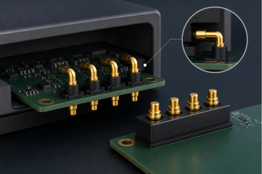
A right angle pogo pin uses the same fundamental spring-loaded mechanism as a standard pogo pin: a plunger sits inside a barrel, held under spring tension, and compresses when it contacts a mating surface. The difference is in the orientation. Where a standard pogo pin makes contact in the same axis as its mounting direction, a right angle pin mounts vertically to the PCB but makes contact horizontally, perpendicular to the board surface.
This ninety-degree change in contact direction sounds like a small modification, but it opens up a completely different range of design possibilities. Instead of requiring a mating surface directly above the PCB, the pin can connect to a contact surface on a side wall, a perpendicular board edge, or any interface that runs parallel to the PCB plane.
The mounting method follows standard pogo pin conventions. Right angle pins are available in through hole configurations where the pin leads pass through drilled holes in the PCB, and in surface mount configurations where they solder directly to surface pads. The choice between these depends on the mechanical requirements of the application and the assembly process, using the same decision logic that applies to standard pogo pin mounting selection.
The Design Problems That Right Angle Pins Solve
The clearest way to understand the value of right angle pogo pins is to look at the specific design problems they resolve that other connector options cannot address as cleanly.
Thin product form factors are the most common driver. When a product has a very low profile housing and the total height from PCB to the opposite surface is insufficient for a vertical pogo pin to function within its working travel range, a right angle pin shifts the contact direction to the side of the housing instead. The pin mounts flat to the board and connects to a contact surface on the enclosure wall, which often has more available clearance than the height dimension.
Side-interface connections in sealed enclosures are another application category where right angle pins are the natural solution. Some products need a charging or data interface on the side of the housing rather than on the bottom or top. Routing a standard vertical pin to a side contact requires additional mechanical components or a flex circuit to redirect the connection, which adds cost and complexity. A right angle pin solves this directly by contacting a pad on the inner wall of the housing or a separate contact strip mounted on the side panel.
Edge-to-edge board connections within multi-PCB assemblies also benefit from right angle pin geometry. When two boards need to communicate and their edges face each other rather than their surfaces, right angle pins on one board can contact pads on the edge or face of the adjacent board without requiring a separate connector housing.
Industries and Applications Where Right Angle Pins Appear Most Frequently
Right angle pogo pins show up across a wider range of product categories than most engineers initially expect, because the underlying problem they solve, connecting in a direction perpendicular to the PCB plane, appears in many different contexts.
Wearable electronics are one of the strongest use cases. Smartwatches, fitness trackers, and medical monitoring devices are designed to be as thin and light as possible. The internal volume available for connectors and interfaces is minimal, and the geometry of a thin wrist-worn device often means that side-interface connections are the only practical option for charging. Right angle pins allow a charging interface to sit on the side of the device housing and connect to the PCB through a compact, reliable spring contact.
Industrial handheld devices and ruggedised equipment use right angle pins when the connection interface needs to be on a specific face of the housing for ergonomic or docking reasons. A handheld scanner that sits in a docking cradle, for example, may use right angle pins to contact charging and data pads in the cradle when inserted from the side rather than the bottom.
Hearing aids and other miniature medical electronics push the size constraints further than almost any other product category. In devices where every cubic millimetre of internal volume is accounted for, the ability to orient a connector in whatever direction the available geometry allows is essential. Right angle pins contribute to this flexibility by allowing the designer to choose the most space-efficient orientation for each interface.
PCB stacking arrangements in compact embedded systems sometimes use right angle pins to create board-to-board connections in tight enclosures where a vertical interface between stacked boards would require more separation than the enclosure height permits.
Key Parameters to Evaluate When Selecting a Right Angle Pin
Selecting a right angle pogo pin involves the same parameter categories as standard pin selection, with a few additional considerations specific to the horizontal contact geometry.
Contact direction and working travel need to be evaluated together with the assembly geometry. The pin extends horizontally from the barrel and compresses when the mating surface pushes back against it. The distance between the pin in its relaxed position and the mating contact surface, across the full dimensional tolerance range of the assembly, needs to fall within the working travel of the pin. Too little distance means the pin cannot extend to contact the mating surface. Too much means the pin is not compressed and cannot exert adequate spring force.
Mounting orientation needs to be confirmed explicitly in the PCB layout so the pin extends toward the intended mating surface, particularly when rotating components to fit tight spaces.
Spring force follows the same logic as standard pins. High enough to maintain reliable contact under vibration and thermal cycling, and low enough that the surrounding structure handles the cumulative load without deforming over the product’s service life.
Plating follows standard pogo pin conventions. Gold over nickel underplating is the standard for stable low contact resistance, with thicker gold specified for interfaces that see frequent connection cycles.
How Right Angle Pins Compare to Alternative Approaches
When engineers encounter a design constraint that a right angle pin can solve, alternative approaches usually come to mind too. Understanding how they compare helps clarify when a right angle pin is the right call.
Flex circuits can redirect a connection from vertical to horizontal, but they add material cost, require extra assembly steps, and introduce failure modes at the bend radius. For a simple two or three pin interface, a right angle pin is almost always the simpler and more reliable solution.
Rigid right angle board-to-board connectors typically need more board space and cannot tolerate misalignment or dimensional variation the way a spring-loaded pin can. Standard connectors with right angle housings also require a mating connector on the other side, adding cost and complexity. When the mating interface is a simple contact pad, a right angle pogo pin eliminates one component from the assembly entirely.
Getting the Geometry Right Before Production
The most common problem with right angle pogo pin implementations is a geometry mismatch that only shows up when physical hardware is assembled for the first time. The pin does not reach the mating surface, or it is over-compressed, or contact is made at an angle that reduces the effective contact area.
Avoiding this requires working through the full dimensional tolerance stack-up during the design phase rather than assuming nominal dimensions represent what production hardware will look like. Confirming that the pin’s working travel accommodates the worst-case assembly variation is the step that separates a right angle pin implementation that works reliably from one that needs rework after the first prototype build.