3R System AK 500 Power Supply Review
Primary Analysis
Contents
On this page we will take an in-depth look at the primary stage of the 3R System AK 500. For a better understanding, please read our “Anatomy of Switching Power Supplies” tutorial.
This power supply uses one U15K80R rectifying bridge, which is not attached to a heatsink. This bridge supports up to 15 A at 100° C, so in theory, you would be able to pull up to 1,725 W from a 115 V power grid. Assuming 80% efficiency, the bridge would allow this unit to deliver up to 1,380 W without burning itself out. Of course, we are only talking about this particular component. The real limit will depend on all the components combined in this power supply.
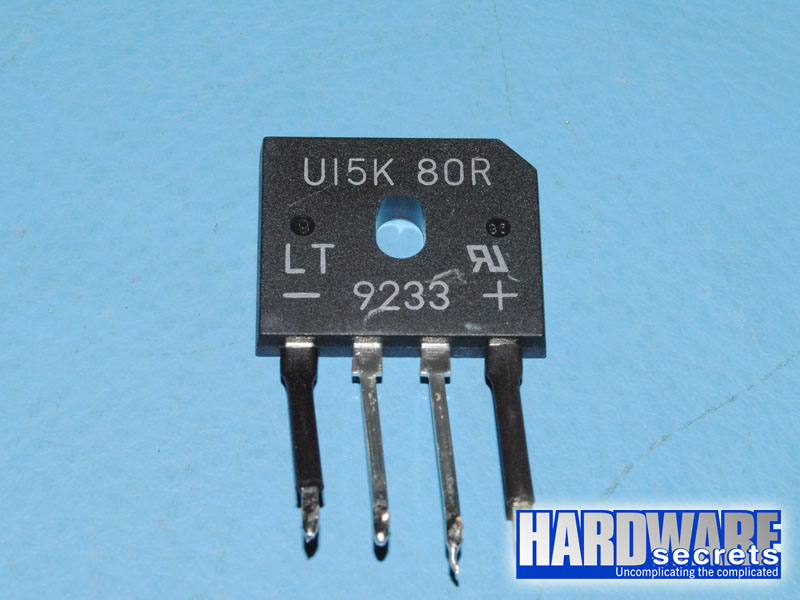 Figure 10: Rectifying bridge
The active PFC circuit uses two MDF18N50 MOSFETs, each supporting up to 18 A at 25° C or 11 A at 100° C in continuous mode (note the difference temperature makes), or 72 A at 25°
; C in pulse mode. These transistors present a 220 mΩ resistance when turned on, a characteristic called RDS(on). The lower the number the better, meaning that the transistor will waste less power, and the power supply will have a higher efficiency.
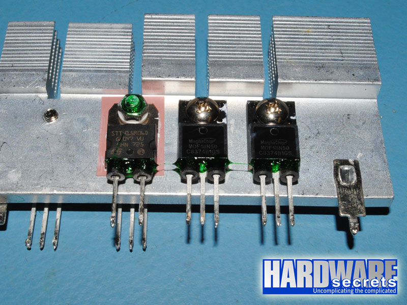 Figure 11: The active PFC diode and transistors
The output of the active PFC circuit is filtered by a capacitor from Samxon, labeled at 105° C.
In the switching section, another two MDF18N50 MOSFETs are used in the traditional two-transistor forward configuration. The specifications for these transistors were discussed above.
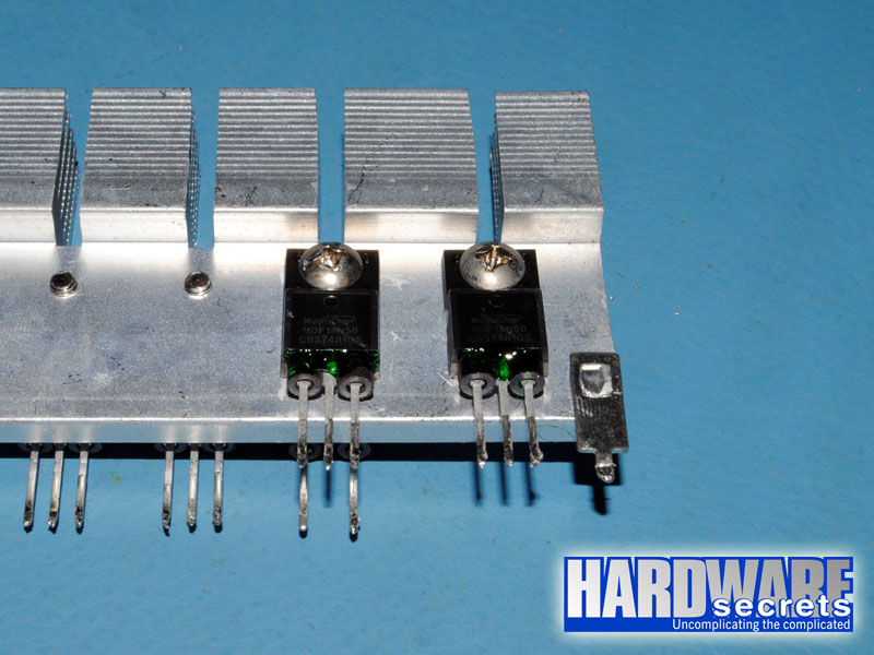 Figure 12: The switching transistors
The primary is controlled by a CM6805 active PFC/PWM combo controller.
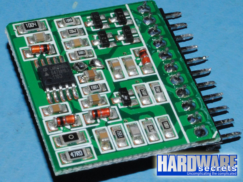 Figure 13: Active PFC/PWM combo controller
Let’s now take a look at the secondary of this power supply.