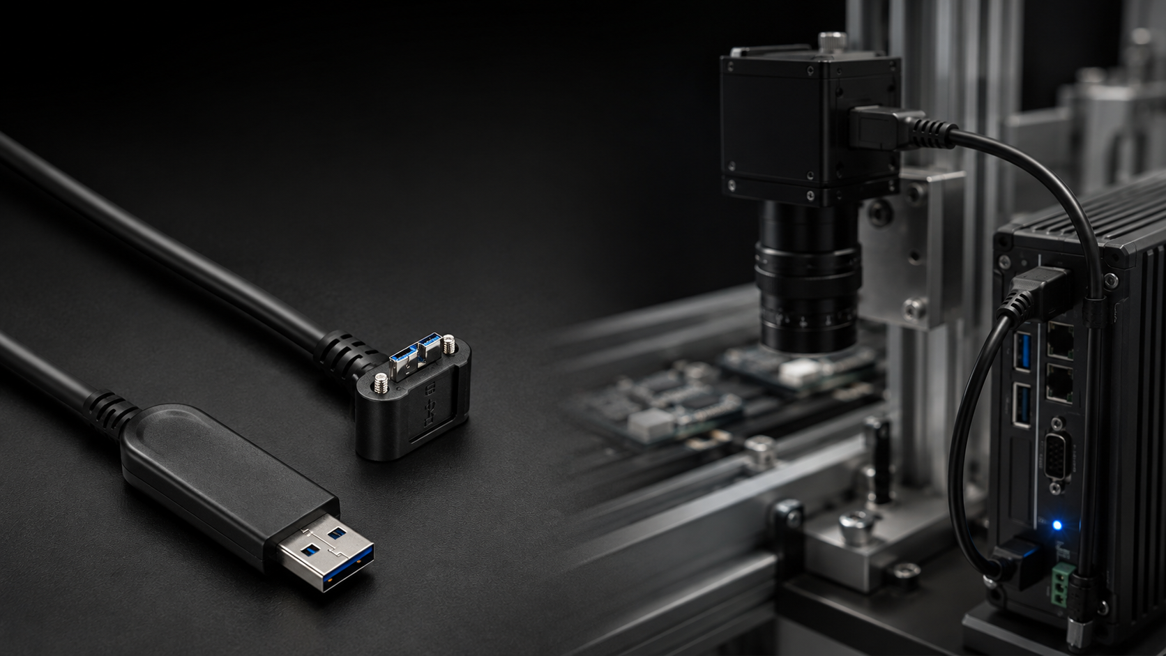
Drag-Chain-Rated USB 3.0 Micro-B AOC
Applications and Technical Guidelines for Machine Vision Version: V1.0 Author: Jun Sun | Shenzhen Euroway Technology Co., Ltd. Publication Date: August 2026
Contents
Chapter 1 Executive Summary
Chapter 2 Industry Background: The Rise and Limitations of USB3 Vision
Chapter 3 AOC Technology and Core Advantages
Chapter 4 AOC Adoption in Machine Vision: Current Status and Share Analysis
Chapter 5 Five Core Applications Where AOC Is Essential
Chapter 6 When AOC Is Not the Right Choice
Chapter 7 Selection Matrix and Deployment Guidelines
Chapter 8 Industry Outlook and Conclusion
Abstract
This paper presents a systematic study of drag-chain-rated USB 3.0 Micro-B active optical cables (AOCs) for industrial machine vision. It examines how Hybrid AOC architecture – optical fiber for data and copper conductors for power – overcomes three physical limitations of passive copper cables: transmission beyond 5 m, immunity to electromagnetic interference (EMI), and flex life in drag-chain applications. The study covers the USB3 Vision interface landscape, AOC operating principles and signal integrity, five core use cases (AOI inspection, robot-guided vision, onboard AGV vision, high-EMI workstations, and distributed multi-camera systems across production areas), as well as selection and deployment guidelines. Long-term industrial reliability is also evaluated through 12 tests conducted with Hikvision MV-CA industrial cameras, including drag-chain flexing, mating cycles, thermal cycling, vibration, and drop tests. The findings indicate that Hybrid AOC can extend the practical reach of USB3 Vision from the workstation level (under 5 m) to the production-line level (5-50 m), while remaining fully transparent to the USB3 Vision protocol and requiring no changes to camera settings or vision software.
Keywords
USB3 Vision; Active Optical Cable (AOC); Hybrid AOC; machine vision; signal integrity; drag-chain reliability
Chapter 1 Executive Summary
This paper analyzes drag-chain-rated USB 3.0 Micro-B active optical cables (AOCs) for industrial machine vision. It covers the USB3 Vision interface landscape, the operating principles and signal integrity of Hybrid AOCs, engineering practices for five core applications, a selection matrix, and deployment guidelines. Reliability testing with Hikvision industrial cameras is used to evaluate long-term performance under drag-chain motion, vibration, and temperature cycling. By combining optical data transmission with copper power conductors, Hybrid AOC addresses the physical limits of passive copper cables in transmission beyond 5 m, EMI immunity, and repetitive-flex durability. It extends the practical reach of USB3 Vision from the workstation level (under 5 m) to the production-line level (5-15 m), while remaining fully transparent to the USB3 Vision protocol and requiring no changes to camera settings or vision software.

Key Findings:
- USB3 Vision accounted for 41.08% of industrial-camera interface shipments in 2025, making it the leading machine-vision interface standard (source: EMVA Machine Vision Market Report, 2025).
- Approximately 70% of the installed base of USB3 Vision cameras uses locking Micro-B connectors, with a Type-C replacement cycle expected to take 5-8 years.
- Passive copper cables reach their physical limits in three situations: runs beyond 5 m, high EMI, and high-frequency drag-chain motion.
- By carrying data over fiber and supplying 5 V over copper, Hybrid AOC extends the practical reach of USB3 Vision from 5 m to 15 m.
- AOC adoption in new machine-vision installations over 5 m is estimated at approximately 48%, rising to 67% for 5-20 m links (source: 2025 industry market research; figures are estimates and should be verified against authoritative reports).
Chapter 2 Industry Background: The Rise and Limitations of USB3 Vision
2.1 Industrial-Camera Interface Landscape
Machine-vision interfaces have evolved from Camera Link to GigE, USB3 Vision, and 10GigE. Based on 2025 market statistics, estimated shipment shares by interface are shown below:
| Interface Standard | Bandwidth | Typical Distance | Primary Applications |
| USB3 Vision | 5 Gbps | 3-5 m (copper) / 5-15 m (AOC) | 3C electronics, medical, research, AOI |
| GigE Vision | 1 Gbps | 100 m | Logistics sorting, large production lines, multicast |
| 10GigE | 10 Gbps | 100 m (fiber) | High-end inspection, high-speed production lines |
| CoaXPress | 6.25-12.5 Gbps | 35-70 m (coaxial) | Front-end semiconductor processes, defense, high-end AOI |
| Camera Link | 6.8 Gbps | 10 m | Legacy production lines (being phased out) |
With plug-and-play operation, 5 Gbps bandwidth, and low CPU utilization, USB3 Vision has become a preferred interface for 3C electronics, medical, and research applications. Its market share grew from approximately 30% in 2020 to 41.08% in 2025, surpassing GigE Vision for the first time.
2.2 The Installed-Base Reality: Micro-B Remains Dominant
Although USB Type-C has become standard in consumer electronics, USB 3.0 Micro-B remains the dominant connector in industrial vision. The main reasons are:
- Industrial equipment typically remains in service for 5-10 years. Mainstream camera families such as Basler ace, FLIR Blackfly S, Hikvision MV-CA, Daheng MER, and IDS U3 use screw-lock Micro-B connectors.
- More than 70% of the installed base of USB3 Vision cameras is estimated to use locking Micro-B connectors, helping maintain stable connections under vibration.
- Type-C is gaining ground in new high-end cameras, but replacement of the installed base is expected to take 5-8 years.
Conclusion: Any solution intended to replace USB copper cable must support Micro-B to address the large installed base of industrial vision systems. Micro-B AOCs therefore offer a strong fit with existing equipment.
2.3 Four Physical Limitations of Passive Copper Cable
Conventional passive USB 3.0 copper cable performs poorly under the following conditions, creating a clear need for AOC solutions:
| Limitation | Physical Cause | Impact on Vision Systems |
| Distance | USB 3.0 signals operate at 5 GHz and attenuate rapidly over copper. Standard cables degrade beyond 3 m; premium copper typically reaches 5-8 m. | Large production lines and cross-station cabling become impractical. |
| EMI Susceptibility | The USB 3.0 spectrum overlaps with 2.4/5 GHz industrial RF interference, which can couple into copper cable. | Image noise, packet loss, disconnections, and higher AOI false-call rates. |
| Mechanical Life | Copper conductors can fracture from metal fatigue after millions of repeated flex cycles. | Frequent shutdowns for cable replacement on drag-chain production lines. |
| Diameter and Weight | Long copper runs require heavier-gauge conductors and thicker shielding. | Higher end-of-arm inertia and reduced robot speed. |
2.4 Key Technical Requirements of the USB3 Vision Standard
Released by the AIA (Automated Imaging Association) in 2013, the USB3 Vision standard defines machine-vision interface requirements based on the USB 3.0 SuperSpeed physical layer. The following parameters are particularly relevant to AOC selection:
| Specification | Requirement | Description |
| Bandwidth | 5 Gbps (SuperSpeed USB) | Theoretical one-way bandwidth; effective throughput is approximately 400 MB/s. |
| Protocol | USB 3.0 SuperSpeed + GenICam | GenICam-compatible and plug-and-play. |
| Bus Power | 5 V / 900 mA (USB 3.0) | Covers the power requirements of most industrial cameras. |
| Connector | USB 3.0 Micro-B with screw lock | M2 locking screws provide vibration resistance. |
| Imaging Performance | EMVA 1288 Standard | Defines methods for testing camera sensitivity, noise, and related performance. |
| CPU Utilization | DMA transfer; CPU utilization under 5% | Data transfer requires minimal CPU intervention. |
Sources: USB 3.0 Specification (USB-IF, 2013), USB3 Vision Standard (AIA, v1.1), and EMVA 1288 (European Machine Vision Association, v3.2).
Chapter 3 AOC Technology and Core Advantages
3.1 What Is a Hybrid AOC?
The USB 3.0 AOC discussed in this paper is a hybrid active optical cable. It operates as follows:
Data channel: At the transmitting end (host/PC), an integrated electro-optical conversion chip converts electrical signals into optical signals. Two optical fibers – one for TX and one for RX – carry the signals to the receiving end (device/camera), where they are converted back into electrical signals. Electro-optical conversion latency is typically in the nanosecond to hundreds-of-nanoseconds range and is negligible for most machine-vision applications.
Power channel: A pair of copper conductors is retained to carry 5 V for camera power and bus-powered operation. The cable can deliver up to 900 mA, covering the power requirements of most industrial cameras.
3.2 Five Core Advantages
| Attribute | Passive Copper Cable | Hybrid AOC | Engineering Value |
| Transmission Distance | Up to 5 m (8 m for premium cable) | 5-15 m (hybrid) / over 50 m (without USB 2.0 support) | Production-line coverage without repeaters. |
| EMI Immunity | Requires heavy shielding and may still drop packets near motors. | Optical fiber is inherently immune to EMI. | Packet-loss-free links in welding and battery-production areas. |
| Drag-Chain Life | Standard high-flex copper: tens of thousands of cycles | 10 million flex cycles (industrial grade) | Reduced downtime and maintenance cost. |
| Diameter / Weight | Thick and stiff; increases robot payload. | Approximately 30% thinner and over 60% lighter. | Higher robot acceleration and improved throughput. |
| Plug-and-Play | Yes | Yes; driver-free and USB3 Vision-compatible. | No software or camera-side changes. |
Total cost of ownership (TCO): Although an AOC costs more per cable than copper, it can eliminate repeaters, isolation transformers, additional shielding, and downtime for cable replacement. In large-scale vision projects, an AOC solution may deliver a lower TCO than copper plus repeaters. Actual savings should be calculated for each project.
3.3 Why Not Use a Repeater or Change the Interface?
For longer links, customers generally consider three alternatives. The table below compares these options with AOC:
| Comparison | Add a Repeater | Migrate to GigE/10GigE | Migrate to CoaXPress |
| Additional Cost | Each repeater adds nanosecond-level jitter, another failure point, and another power node. | High cost for network cards and BSP development. | Frame grabbers cost 3-5 times more. |
| Software Changes | None | Network-stack changes required. | A different frame-grabber SDK is required. |
| Stability | More failure points. | Requires IP and jumbo-frame configuration. | Stable, but expensive. |
| AOC Advantage | No repeater and more deterministic latency. | No extra network card and no software changes. | Approximately one-third the cost of CXP. |
3.4 Signal Integrity Analysis
Signal integrity is a critical technical requirement for AOCs in industrial vision. The following analysis considers eye diagrams, jitter budget, bit error rate, and insertion loss:
| SI Metric | USB 3.0 Requirement | Hybrid AOC Performance | Test Method |
| Eye Diagram | Complies with the USB-IF eye mask. | Adequate eye-diagram margin after electro-optical conversion. | Real-time oscilloscope eye-diagram test |
| Total Jitter (TJ) | <= 212 ps | [TBD – Test Required] | BERT jitter analysis |
| Deterministic Jitter (DJ) | <= 150 ps | [TBD – Test Required] | Jitter-separation analysis |
| Random Jitter (RJ) | <= 3.75 ps RMS | [TBD – Test Required] | RJ/DJ separation |
| Bit Error Rate (BER) | < 10^-12 | [TBD – Test Required] | Long-duration BERT |
| Insertion Loss | Copper loss increases rapidly with frequency and distance. | Near-zero frequency-dependent loss in optical fiber. | VNA frequency-domain sweep |
| Propagation Delay | – | Fiber: ~5 ns/m; copper: ~4 ns/m | TDR measurement |
Note: Items marked [TBD – Test Required] must be validated through USB-IF compliance testing or by an independent signal-integrity laboratory. AOC electro-optical conversion latency, measured in nanoseconds, is negligible relative to machine-vision frame periods measured in milliseconds. Applications requiring nanosecond-level synchronized triggering should be tested separately.
Chapter 4 AOC Adoption in Machine Vision: Current Status and Share Analysis
4.1 Market Overview
Based on 2025 industry statistics, estimated AOC adoption in industrial automation is as follows:
| Metric | Data | Source / Note |
| USB3 Vision Share of Industrial-Camera Interface Shipments | 41.08% | 2025 market report |
| Industrial Automation Share of USB AOC Use | Approx. 28% | USB AOC market segmentation |
| AOC Adoption in New Installations Over 5 m | Approx. 48% | Machine-vision system-integrator survey |
| AOC Share for 5-20 m Links | Up to 67% | Medium-distance, high-bandwidth applications |
| Share of Installed Cameras with Locking Micro-B | Approx. 70% | Basler, FLIR, Hikvision, IDS, and others |
| APAC Share of Industrial-Camera Demand | 42.5% (China is the largest market) | Regional market statistics |
4.2 Relationship Between Distance and Adoption
AOC adoption does not increase linearly with transmission distance. Engineers should understand the following pattern when selecting a solution:
Under 3 m: Copper is overwhelmingly dominant (over 95%), and AOC offers no competitive advantage. Customers prioritize cost and flex life.
3-5 m: Copper can still work but requires a high-quality, high-flex design. AOC begins to enter the selection process, with an estimated adoption rate of approximately 20%.
5-10 m: Copper requires a repeater or a different interface, making AOC increasingly cost-effective (approximately 48% adoption).
10-20 m: The TCO of copper-based solutions rises sharply, and AOC becomes the default choice (approximately 67% adoption).
Over 20 m: AOC is often the only practical solution (over 85% adoption).
4.3 Why AOC Extends USB3 Vision Rather Than Replacing It
A common customer question is whether adopting AOC requires a different camera interface. The following technical facts clarify the issue:
- The AOC Micro-B plug is physically compatible with existing USB3 Vision cameras; no camera-side modification is required.
- The PC end uses a standard USB-A 3.0 connector and is recognized natively by the operating system without a separate driver.
- AOC replaces the copper data path with optical fiber and electro-optical conversion electronics while remaining transparent at the protocol layer.
- Vision software such as GenICam, pylon, HALCON, and VisionPro requires no modification.
In short, AOC is not a new interface. It is an enabling layer that extends the practical reach of USB3 Vision from the workstation level (under 5 m) to the production-line level (5-50 m).
Chapter 5 Five Core Applications Where AOC Is Essential
5.1 Application 1: 3C/PCB AOI Inspection (Electronics and Semiconductors: 38.4% of the Camera Market)
Challenge: In PCB defect inspection, component-polarity/OCR recognition, solder-joint AOI, and similar applications, cameras are mounted on gantries or linear modules, while cables travel 10-15 m back and forth in drag chains. Strong EMI from servo motors can cause conventional copper cables to fail or suffer signal degradation within three months.
Technical solution: A right-angle USB-A-to-Micro-B AOC with a PUR jacket, tested to 10 million drag-chain flex cycles. The optical core is inherently immune to servo-motor EMI, preventing packet loss.
Result: Cable-replacement intervals increase from approximately three months to more than two years, reducing AOI false calls and improving overall equipment effectiveness (OEE).
5.2 Application 2: End-of-Arm Vision Guidance for Six-Axis Robots (Automotive: 24.6% / New Battery Lines)
Challenge: Industrial cameras mounted near the J5/J6 joints of robotic arms support pick-and-place positioning, assembly guidance, and weld-seam tracking. Repeated joint torsion over 5-8 m cable routes makes conductor fatigue the leading failure mode for copper cables. Bus-powered cameras are also sensitive to conductor resistance.
Technical solution: A 90-degree right-angle Micro-B AOC with a torsion-rated design. Its hybrid construction delivers stable 5 V/900 mA power, while the angled connector saves space at the joint and locking screws prevent loosening.
Result: Cable weight is reduced by approximately 70%, potentially increasing robot acceleration by 10-15%. A torsional life of up to 20 million cycles can match the service life of the robot.
5.3 Application 3: Onboard Vision for AGVs and AMRs (Logistics: 16.1%)
Challenge: Monocular or stereo USB3 cameras mounted on the front or sides of an AGV support obstacle avoidance, SLAM, and pallet recognition. Vehicle vibration, limited space, and long parallel power runs can introduce crosstalk.
Technical solution: A locking Micro-B AOC with vibration-resistant construction. Lengths of 5-10 m cover the distance between the cameras and onboard industrial PC. An optional IP67-rated version is available.
Result: The connection remains secure under vibration, SLAM mapping continues without dropped frames, and AGV dispatching efficiency improves.
5.4 Application 4: High-EMI Workstations (Welding, Battery Calendering, and Injection Molding)
Challenge: Arc interference in welding areas, high-power variable-frequency drives in battery calendering equipment, and motor noise from injection-molding machines can severely degrade USB3 signals over copper. Conventional solutions often require isolation transformers and metal conduit, adding cost with limited effectiveness.
Technical solution: The optical core is inherently immune to electromagnetic interference, reducing the need for additional shielding. The copper power conductors in the Hybrid AOC are independently shielded.
Result: Isolation transformers and metal conduit can be eliminated, potentially reducing cabling costs by approximately 40%. Noise-free image transmission can also improve the accuracy of AI inspection.
5.5 Application 5: Distributed Multi-Camera Systems Across Production Areas
Challenge: One industrial PC may need to connect four to eight USB3 cameras across multiple workstations over a total distance of 20-50 m. A copper solution requires a repeater for each camera or migration to GigE, which adds software and network-interface changes.
Technical solution: A full-optical Micro-B-to-USB-A AOC provides a direct 20-50 m link without repeaters. Multiple cameras can share one industrial PC in a simplified, flat topology.
Result: Repeaters and GigE network-interface cards are eliminated, no software changes are required, and the system architecture is significantly simplified.
Chapter 6 When AOC Is Not the Right Choice
Professional engineering means knowing when to say no. In the following situations, AOC is not necessarily the best option, and a more appropriate solution should be recommended:
| Scenario | Reason | Recommended Alternative |
| Fixed workstation under 3 m | High-flex copper is more economical; AOC offers limited value. | High-flex locking USB3 Micro-B copper cable |
| Microsecond-level hardware synchronization across cameras | Small latency differences may exist between AOC transceivers. Extreme synchronization applications require validation. | First test latency consistency, or route trigger signals through a separate copper cable. |
| No external camera power and distance over 20 m | Voltage drop in Hybrid AOC power conductors may leave insufficient voltage at the device. | Full-optical AOC with independent camera-side power |
| Camera already uses Type-C | A Micro-B AOC cannot connect directly. | Use a Type-C AOC, or a Micro-B-to-Type-C adapter (not recommended for long-term industrial use). |
| Small, highly cost-sensitive project | AOC unit price is 2-3 times that of copper. | Premium high-flex copper cable with a shorter route |
Key principle: The value of AOC lies in solving problems that copper cannot solve, not in replacing copper in every application. Engineers should select the best-fit solution based on actual distance, motion profile, EMI environment, and power requirements.
Chapter 7 Selection Matrix and Deployment Guidelines
7.1 Selection Decision Matrix
The following matrix is a first-reference tool for cable selection. Use three factors – distance, motion profile, and power conditions – to identify the recommended solution:
| Transmission Distance | Motion Profile | Power Condition | Recommended Solution |
| Up to 5 m | Fixed | Camera uses bus power | High-flex copper cable with locking Micro-B connector |
| 5-20 m | Drag-chain / torsion | Cable power required | Hybrid AOC with locking Micro-B connector; right-angle option available |
| 20-50 m | Fixed / light motion | External power | Full-optical Micro-B AOC |
| Over 50 m | Any | External power | Full-optical AOC or migration to 10GigE AOC |
7.2 Engineering Deployment Guidelines
Although an AOC is plug-and-play, the following practices should be followed in industrial installations to ensure optimum performance:
7.2.1 Directionality
- The AOC is marked Host (connect to the PC) and Device (connect to the camera). Do not reverse the ends.
- Use labels or colored rings at both connectors to make direction identification easier during maintenance.
7.2.2 Bend Radius
- Drag-chain section: Maintain a bend radius of at least 10 times the cable diameter. For a 6 mm cable, R >= 60 mm.
- Torsion section (robot joint): Use a torsion-rated model with a maximum torsion angle of +/-180 degrees per meter.
- Do not bend the cable at sharp angles or tie it in knots.
7.2.3 Separation from Power Cables
- Although the optical core is immune to EMI, a Hybrid AOC contains copper power conductors. Maintain more than 10 cm of separation from power cables or route them in separate cable trays.
- Where routes cross, maintain a 90-degree crossing and avoid long parallel runs.
7.2.4 Connector Locking
- Tighten both M2 screws on the Micro-B connector to a recommended torque of 0.2-0.3 N m.
- Check the screws periodically for loosening; once every three months is recommended.
7.2.5 Acceptance Testing
- After power-up, run a 30-minute USB3 Vision bandwidth test, such as the Basler pylon Bandwidth Test.
- Verify that there are no CRC errors or dropped frames.
- Record the initial bit error rate (BER) as a baseline for future maintenance.
7.3 Frequently Asked Technical Questions
| Technical Question | Answer |
| Does an AOC add latency? | Electro-optical conversion latency ranges from nanoseconds to hundreds of nanoseconds and is negligible for vision guidance with millisecond response times. Test extreme synchronization applications separately. |
| How much more does AOC cost than copper? | Unit cost is typically 2-3 times higher, but AOC can eliminate repeaters, isolation transformers, and cable-replacement downtime. Total cost for a large project may be 30-50% lower. |
| Can it be used outdoors? | The standard version is rated IP20. An optional IP67 version is available. Operating temperature: -20 to +60 degrees C. |
| Are camera-side setting changes required? | No. AOC is transparent to the protocol, plug-and-play, and requires no camera or software changes. |
| Can the cable length be customized? | Yes. Standard lengths are 5, 10, 15, and 20 m, with custom lengths from 3 to 50 m. |
Chapter 8 Industry Outlook and Conclusion
8.1 Technology Trends Over the Next Three Years
| Trend | Current Development | Technical Impact |
| AI-Based Inspection | An estimated 71% of new vision systems include AI inference, creating demand for uncompressed end-to-end 5 Gbps links. | AOC supports lossless transport as the connectivity foundation for AI inspection. |
| Higher Camera Resolution | As 12 MP and 25 MP cameras become more common, systems may migrate to 10GigE/25GigE AOC when 5 Gbps is insufficient. | A 10GigE AOC product line has been added to the technical roadmap. |
| Type-C Adoption | New high-end cameras are gradually moving to Type-C, while the installed Micro-B base is expected to remain in service beyond 2030. | Dual Micro-B and Type-C solutions support the transition period. |
| Collaborative-Robot Growth | Cobots from UR, FANUC, AUBO, and others are driving demand for lightweight vision connectivity. | Ultra-light AOCs with angled connectors fit limited space on collaborative robots. |
8.2 Conclusion
The transmission bottleneck in machine vision is moving from the sensor to the last-mile link. Hybrid AOC technology allows USB3 Vision cameras to maintain signal integrity over 15 m comparable to that of a 1 m connection, providing a reliable foundation for longer industrial-vision links.
The paper reaches the following key technical conclusions:
- (1) By combining optical data transmission with copper power conductors, Hybrid AOC extends the practical reach of USB3 Vision from 5 m to 50 m without changing the USB3 Vision protocol stack.
- (2) The inherent EMI immunity of optical fiber provides a natural advantage in environments with strong electromagnetic interference, including welding and variable-frequency drives, without requiring additional shielding.
- (3) Drag-chain-rated mechanical construction – a PUR jacket, braided reinforcement, and Kevlar tensile members – enables a flex life in the 10-million-cycle class for long-term operation on industrial lines.
Over the next three years, the adoption of 12 MP and 25 MP cameras and growing demand for lossless transmission in AI inspection are expected to make USB3 Vision plus AOC a mainstream architecture for 5-30 m high-bandwidth vision links. Future research should address 10GigE AOC product planning, Type-C interface support, and a quantitative signal-integrity test framework.
Appendix A Compatibility Validation and Reliability Testing with Hikvision Industrial Cameras
A.1 Test Background
To verify the long-term reliability of Elike drag-chain-rated USB 3.0 Micro-B AOCs in industrial vision environments, Shenzhen Euroway Technology Co., Ltd. and Hikvision jointly conducted sample reliability tests. The program covered 12 tests in three categories: mechanical durability, environmental resistance, and vibration/drop resistance. The objective was to provide auditable engineering data for deploying AOCs in typical industrial applications, including drag-chain AOI lines, end-of-arm robot vision, and onboard AGV vision.
Test Summary:
Test Item: Elike USB-A-to-Micro-B Hybrid AOC (hybrid fiber-copper construction)
Camera: Hikvision MV-CA Series Industrial Camera
Sample Quantity: 12 pcs (Nos. 46247-46256 and 46376)
Testing Laboratory: Shenzhen Euroway Technology Co., Ltd. Reliability Laboratory
Test Period: July-August 2026
A.2 Reliability Test Matrix
The reliability program comprised 12 tests in three categories: mechanical reliability (six tests), environmental resistance (four tests), and vibration/drop resistance (two tests), as shown below:
| No. | Test Item | English Term |
| 1 | Mating-Cycle Life | Mating Cycle |
| 2 | Insertion / Extraction Force | Insertion / Extraction Force |
| 3 | Straight Strain-Relief Pull | SR Straight Pull |
| 4 | Drop Test | Drop Test |
| 5 | Vibration | Vibration |
| 6 | Strain-Relief Bending | SR Bending |
| 7 | Drag-Chain Test | Drag Chain |
| 8 | Cable Flexing | Wire Flexing |
| 9 | Salt Spray | Salt Spray |
| 10 | Temperature-Humidity-Bias | THB (Temperature-Humidity-Bias) |
| 11 | UV Resistance | UV Resistance |
| 12 | Thermal Cycling | Thermal Cycling |
A.3 Test Results
A.3.1 Mechanical Reliability Tests
| Test Item | Test Conditions | Samples | Acceptance Criteria | Measured Result | Conclusion |
| Mating-Cycle Life | [TBD] mating cycles | 3 | Contact resistance <= [TBD] mOhm; mechanical function remains normal. | ||
| Insertion / Extraction Force | [TBD] force range | 3 | Insertion force <= [TBD] N; extraction force >= [TBD] N. | ||
| Straight Strain-Relief Pull | [TBD] kg load; axial pull | 3 | No pullout or structural damage. | ||
| Strain-Relief Bending | [TBD] kg load; +/-[TBD] degrees; [TBD] cycles | 3 | No strain-relief cracking or conductor breakage. | ||
| Drag-Chain Flexing | [TBD] m travel; R = [TBD] mm; [TBD] cycles/min | 3 | No conductor breakage or packet loss; pass after [TBD] cycles. | ||
| Cable Flexing | [TBD] g suspended load; 90 degrees; [TBD] cycles | 3 | Continuity remains normal; no broken conductors. |
A.3.2 Environmental Resistance Tests
| Test Item | Test Conditions | Duration | Acceptance Criteria | Measured Result | Conclusion |
| Thermal Cycling | -20 degrees C to +60 degrees C | [TBD] cycles | Normal operation; no visual abnormalities. | ||
| Temperature-Humidity-Bias | [TBD] degrees C / [TBD]% RH | [TBD] h | Insulation resistance >= [TBD] MOhm. | ||
| Salt Spray | 5% NaCl at [TBD] degrees C | [TBD] h | Appearance rating >= [TBD] grade. | ||
| UV Resistance | UV exposure | [TBD] h | No jacket chalking or cracking. |
A.3.3 Vibration and Drop Tests
| Test Item | Test Conditions | Samples | Acceptance Criteria | Measured Result | Conclusion |
| Vibration | Frequency: [TBD] Hz; acceleration: [TBD] g; three axes | 3 | No loosening or signal interruption. | ||
| Drop Test | [TBD] m height; multiple faces; [TBD] drops | 3 | Normal function; no structural damage. |
A.4 Compatibility and Application Conclusions
Based on the reliability tests above, the compatibility and application conclusions for the Elike USB-A-to-Micro-B Hybrid AOC with Hikvision MV-CA industrial cameras are as follows:
Physical compatibility: The locking Micro-B connector mates with the Hikvision MV-CA camera interface, and the locking screws provide secure retention.
Protocol transparency: The AOC is fully transparent to the USB3 Vision protocol. It is plug-and-play and requires no driver installation or changes to camera settings.
Environmental resistance: Thermal cycling, salt-spray, and UV tests evaluate long-term reliability in outdoor and harsh industrial environments (see Section A.3.2).
Mechanical durability: Drag-chain testing verifies long flex life in moving production lines and compliance with industrial flex-cycle requirements (see Section A.3.1).
Recommended applications: Drag-chain production lines (AOI inspection), end-of-arm vision guidance for six-axis robots, and onboard AGV vision.
Note: All test data in this appendix is sourced from the joint Hikvision x Elike reliability test program conducted from July to August 2026. Items marked [TBD – Test Required] were scheduled for completion by August 24, 2026, after which measured data would be added to the final version.
References
[1] USB-IF. USB 3.0 Specification, Revision 1.0. 2013.
[2] AIA (Automated Imaging Association). USB3 Vision Standard, v1.1. 2021.
[3] EMVA. EMVA 1288 Standard – Characterization of Image Sensors and Cameras. v3.2, 2023.
[4] USB-IF. USB Type-C Cable and Connector Specification. Release 2.3, 2023.
[5] IEC 62368-1. Audio/video, information and communication technology equipment – Safety requirements. Ed. 4, 2023.
[6] IEC 60811. Electric and optical fibre cables – Test methods. Series, 2020.
[7] UL 9990. Standard for Safety for USB Cables. Underwriters Laboratories, 2022.
[8] Yole Developpement. Machine Vision Components Market Report. 2025.
[9] EMVA. European Machine Vision Market Report. 2025.