• Skip to primary navigation
  • Skip to main content
  • Skip to primary sidebar
  • Skip to footer
Hardware Secrets

Hardware Secrets

Uncomplicating the complicated

  • Case
  • Cooling
  • Memory
  • Mobile
    • Laptops
    • Smartphones
    • Tablets
  • Motherboard
  • Networking
  • Other
    • Audio
    • Cameras
    • Consumer Electronics
    • Desktops
    • Museum
    • Software
    • Tradeshows & Events
  • Peripherals
    • Headset
    • Keyboard
    • Mouse
    • Printers
  • Power
  • Storage
Home » Anatomy of a Hard Disk Drive

Anatomy of a Hard Disk Drive

[nextpage title=”Introduction”]

We disassembled a hard drive to show you the main components you will find on a hard drive.

Hard drives have two kinds of components: internal and external. External components are located on a printed circuit board called logic board while internal components are located in a sealed chamber called HDA or Hard Drive Assembly.

Anatomy of a Hard Disk Drive
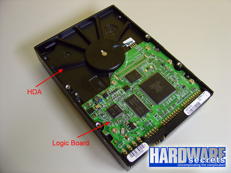
Figure 1: A Hard Disk Drive.

You cannot open a hard drive or you will make your drive unusable. Hard drives are assembled in clean rooms (cleaner than surgery rooms) and then sealed. Any particle of dust inside the HDA can destroy the surface of the discs, because the discs spin at a very high speed (at least 5,400 rpm nowadays). This would not only lead to data loss, but also the physical destruction of the disc surface.

So, there is no serviceable part inside the HDA – at least for the regular technician. Only data recovery companies with clean rooms can open and replace components inside the HDA. Anyway, before exploring the components located both the logic board and inside the HDA, let’s take a look at the connectors found on a regular hard drive.

[nextpage title=”Connectors”]

Hard disk drives have basically two connectors, one for power and other for exchanging data with the computer. This second connector is better known as “interface”. The most common hard disk drive interface for end-users is called ATA (Advanced Technology Attachment), while SATA (Serial ATA) interface was created to replace ATA and is becoming more popular these days. After the released of SATA, ATA interface started being also called PATA (Parallel ATA). Another famous interface is called SCSI (Small Computer Systems Interface), but it is targeted to servers and rarely seen on PCs targeted to end-users.

Hard Disk Drive ConnectorsFigure 2: Connectors on a hard disk drive using ATA interface.

The master/slave jumper on ATA hard drives can be configured in three different ways:

  • Master: this means that this drive will be the only one attached to the cable that connects the hard drive to the computer or will be the first drive in a two-drive configuration.
  • Slave: this means that this drive will be the second drive attached to the cable that connects the hard drive to the computer.
  • CS (Cable Select): this means that you will use a “special” cable (called CS cable) that the configuration of whether a drive will be master or slave will be made by the position of the hard drive on the cable and not by a jumper configuration on the drive.

Hard Disk Drive ConnectorsFigure 3: Connectors on a hard disk drive using SATA interface.

Serial ATA standard introduced a new power supply plug, which is very different from the standard hard drive power plug. Since Serial ATA is still entering the market, you will find a lot of Serial ATA hard drives with both power connectors, like the one in Figure 3. You need to use just one of them, not the two at the same time.

To learn more about ATA and Serial ATA, we’ve written a complete tutorial on ATA drives and a complete tutorial on Serial ATA drives.

Let’s move on and talk about the components on the logic board.

[nextpage title=”Logic Board”]

On the logic board you will find all circuitry in charge of controlling the hard drive. In these days of highly integrated devices, you will find just three or four big integrated circuits on the logic board, as you can see on Figures 4 and 5. Take a look at the pictures as we will explain more about the circuits pictured below.

Hard Disk Drive Logic BoardFigure 4: Logic board from an ATA hard drive.

Hard Disk Drive Logic BoardFigure 5: Logic board from a SATA hard drive.

The big circuit is the controller. It is in charge of everything: exchanging data between the hard drive and the computer, controlling the motors on the hard drive, commanding the heads to read or write data, etc.

Optionally there is a Flash-ROM circuit where the hard drive firmware is located. Firmware is the name given to a program that is stored inside a ROM (Read Only Memory). The hard drive firmware is the program its controller executes. Sometimes this device is embedded in the controller, as it happens on the hard drive in Figure 5.

The controller doesn’t drive enough current to turn on or move the hard drive motors. So all hard drives use a motor driver chip. This chip is a current amplifier. It takes the commands sent from the controller to the motors and passes them to the motors, but with a higher current. So, this chip is located between the controller and the motors.

The fourth main chip you can find on a logic board is the RAM (Random Access Memory) chip, also known as buffer. This chips has an ultimate role in the hard drive performance. The higher its capacity, the fastest the data transfer between the drive and the computer will be. You can find out the capacity of your hard drive buffer on the chip manufacturer’s website. For example, the memory chip in Figure 4 is a Hynix HY57V161610DTC chip. Going to Hynix’s website at https://hynix.com/datasheet/eng/dram/details/dram_01_HY57V161610DTC.jsp you can find this is a 16 Mb (Megabit) chip. The capacity of memory chips is given in Megabits, while we use Megabyte to refer to memory capacity. Thus we need to divide the value given in Megabit by eight in order to have the value in Megabyte. So, this chip is a 2 MB (Megabyte) chip, so this hard drive buffer is of 2 MB.

In Figure 5, you can see another chip, which is a SATA/ATA converter chip. A lot of manufacturers instead of designing Serial ATA controller chips simply pick ATA controller chips and add a converter chip to convert the hard drive Serial ATA interface into regular ATA. This is the case of the hard drive in Figure 5, which uses the Marvell 88i8030 converter chip. So even though this hard drive has a Serial ATA interface, it is not a “true” Serial ATA hard drive (it is not a “native” Serial ATA hard drive), since its controller chip is still ATA.

You may be wonder how do we know the function of each chip on the logic board. Actually it is fairly simple and you can learn the trick from us. Just type in the numbers located on the first line of the chip package on Google and it will return a lot of information about the chip! For example, for the Flash-ROM used on the hard drive in Figure 4, just type in M29F102BB and the first item returned will be a page on ST Microelectronics with all technical details of this chip.

[nextpage title=”Spindle Motor”]

In Figure 6 we show the H.DA after we removed the logic board. There you can clearly see the spindle motor and its contacts – which connect this motor to the logic board –, and also the contacts from the devices inside the HDA, namely the heads and the voice coil actuators.

Spindle MotorFigure 6: HDA without the logic board.

On hard drives targeted to desktops, the spindle motor rotates at 5,400 rpm, 7,200 rpm or even 10,000 rpm, depending on the drive. The faster this motor rotates, the faster data can be read from the platters. Hard drives targeted to laptops usually rotates at 4,200 rpm.

[nextpage title=”Inside the HDA”]

We removed the hard drive cover to show you how it looks like inside. Do not do this with you hard drive or you will damage it. If you are curious, open only defective hard drives (our hard drive was defective).

Hard Disk DriveFigure 7: Main parts inside a hard drive.

The connector you see in Figure 7 is the opposite side of the connector in Figure 6.

The hard drive can have several discs. The one on our picture had three discs. There is one read/write read for each side of the disc – which is also called platter. The heads are stuck together in an arm. So, all the heads move together.

Hard Drive PlattersFigure 8: Several discs inside a hard drive.

A motor (actually the correct term is “actuator”) called voice coil moves the arm. It is called “voice coil” because it uses the same idea behind loudspeakers: a coil inside a magnetic field provided by a magnet. Depending on the current direction on the coil the arm moves to one side or to the other side. And depending on the intensity of the current, the actuator will move more or less. We removed the top “cover” (actually the top magnet) from voice coil and you can see it disassembled in Figure 9.

Voice CoilFigure 9: Voice coil actuator.

We removed the arm from the hard drive. You can see it in Figure 10. While we were removing it, we broke one of the heads (ops!). So, it should have six heads there but you will only see five (sorry, chief!)

Hard Disk Drive HeadsFigure 10: Hard drive heads.

Reader Interactions

Leave a Reply Cancel reply

Your email address will not be published. Required fields are marked *

Primary Sidebar

As a participant in the Amazon Services LLC Associates Program, this site may earn from qualifying purchases. We may also earn commissions on purchases from other retail websites.

car service

Why Is Fleet Maintenance Important?

If you have a fleet of vehicles you use within your business, it’s crucial you keep up with their

Playing Fifa on Play station 4

Tips for Recycling Your Gaming Consoles and Devices

These days, it seems like almost everybody is gaming. As great as this is, it’s also creating a

Business planning

How to Develop Your Venture Capital Business

Venture Capital (VC) is a type of private equity investment in which investors provide funding to

Footer

For Performance

  • PCI Express 3.0 vs. 2.0: Is There a Gaming Performance Gain?
  • Does dual-channel memory make difference on integrated video performance?
  • Overclocking Pros and Cons
  • All Core i7 Models
  • Understanding RAM Timings

Everything you need to know

  • Everything You Need to Know About the Dual-, Triple-, and Quad-Channel Memory Architectures
  • What You Should Know About the SPDIF Connection (2022 Guide)
  • Everything You Need to Know About the Intel Virtualization Technology
  • Everything You Need to Know About the CPU Power Management

Copyright © 2023 · All rights reserved - Hardwaresecrets.com
About Us · Privacy Policy · Contact