[nextpage title=”Introduction”]
Instead of releasing a longer 850 W power supply, Antec decided to build a taller unit. Because of it is bigger, CP-850 only fits a few cases from Antec (Twelve Hundred, P183 and P193). Is it a better solution that regular-sized units? Let’s see.
Antec CP-850 is 4 23/32” (12 cm) tall, while regular power supplies are 3 11/12 (8.5 cm) tall. It is 6 ½” (16.5 cm) deep, but because its 120 mm fan is located outside the power supply housing, it is actually 7 43/64” (19.5 cm) deep. It is also wider than regular units, measuring 6 57/64” (17.5 cm) against 5 29/32” (15 cm).
Like Antec Signature series, CP-850 is manufactured by Delta Electronics.
Figure 1: Antec CP-850 power supply.
Figure 2: Antec CP-850 power supply.
Figure 3: Antec CP-850 installed inside an Antec P183 case.
Figure 4: Half modular cabling system.
All cables that come from inside the power supply use a nylon protection, but this protection does not come from inside the power supply housing.
This unit uses a half modular cabling system. The main motherboard cable (20/24-pin), the EPS12V cable, the ATX12V cable, two cables with one six/eight-pin connector for video cards each, one cable containing three SATA power connectors and one cable with three standard peripheral power plugs and one floppy disk drive power plug come straight from the power supply.
The modular cabling system provides four connectors, two for auxiliary video card power connectors (the unit comes with two cables with one six-pin video card auxiliary power connector each) and two for peripheral power connectors, and the unit comes with four cables (two cables with three standard peripheral power plugs each and two cables with three SATA power plugs each), so you can choose two from these four cables.
The number of power connectors available is more than enough for most users, however very high-end enthusiasts may face some challenges, as you won’t be able to install more than two very high-end video cards at the same time with this power supply, since very high-end cards use two auxiliary power connectors each and this unit comes with “only” four connectors. The solution in this case is to convert standard peripheral power plugs into video card auxiliary power connectors using adapters.
All wires are 18 AWG, which is the correct gauge to be used.
The distance between the power supply housing and the first connector on each cable is of 25 19/32” (65 cm) and the distance between each connector on cables that have more than one plug is of 6 29/32” (15 cm). The cables are very long, compatible with the full-tower cases this power supply is targeted to.
Figure 5: Cables.
Now let’s take an in-depth look inside this power supply.
[nextpage title=”A Look Inside The CP-850″]
We decided to disassemble this power supply to see what it looks like inside, how it is designed, and what components are used. Please read our Anatomy of Switching Power Supplies tutorial to understand how a power supply works and to compare this power supply to others.
This page will be an overview, and then in the following pages we will discuss in detail the quality and ratings of the components used.
Antec was expecting us to disassemble this unit, as it has its logo inside the power supply.

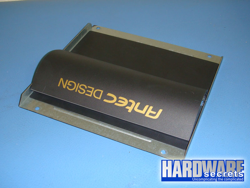
Figure 6: Antec logo on one of the covers.
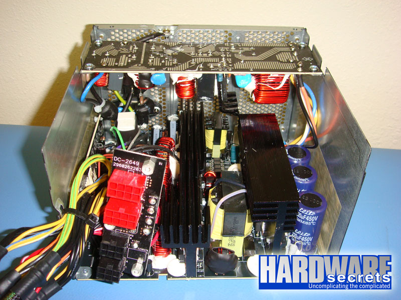
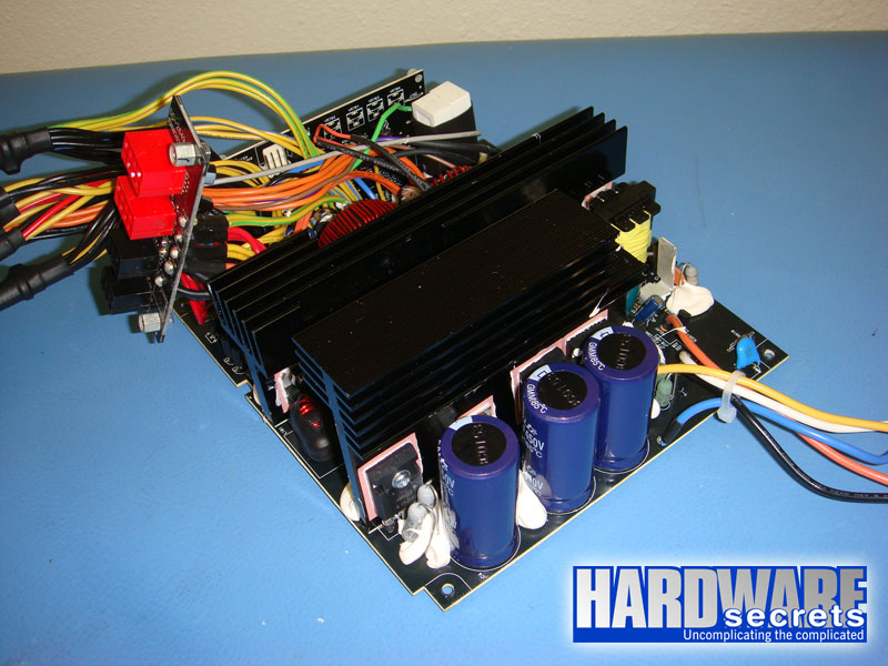
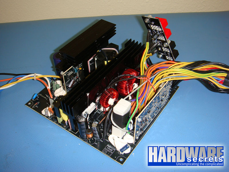
This power supply uses two printed circuit boards, a small one with the transient filtering stage, the rectifying bridge and the PFC coil, and a big one with all other components. The solder side of each board was facing outside the power supply, so the components from the two boards were facing the middle of the power supply, making a tunnel so air could pass and cool the components down.

Figure 7: Overall look.

Figure 8: Overall look.

Figure 9: Overall look.
[nextpage title=”Transient Filtering Stage”]
As we have mentioned in other articles and reviews, the first place we look when opening a power supply for a hint about its quality, is its filtering stage. The recommended components for this stage are two ferrite coils, two ceramic capacitors (Y capacitors, usually blue), one metalized polyester capacitor (X capacitor), and one MOV (Metal-Oxide Varistor). Very low-end power supplies use fewer components, usually removing the MOV and the first coil.
On this power supply this stage is flawless, with two X capacitors, four Y capacitors and one ferrite coil more than required.
Figure 10: Transient filtering stage (part 1).

Figure 11: Transient filtering stage (part 2).
In the next page we will have a more detailed discussion about the components used in the Antec CP-850.
[nextpage title=”Primary Analysis”]
On this page we will take an in-depth look at the primary stage of Antec CP-850. For a better understanding, please read our Anatomy of Switching Power Supplies tutorial.
This power supply uses one D25XB60 rectifying bridge in its primary, which can deliver up to 25 A at 98° C if a heatsink is used, which is the case (without a heatsink the current limit drops to 3.5 A at 25° C). This component is clearly overspec’ed: at 115 V this unit would be able to pull up to 2,875 W from the power grid; assuming 80% efficiency, the bridge would allow this unit to deliver up to 2,300 W without burning this component. Of course we are only talking about this component and the real limit will depend on all other components from the power supply.
Figure 12: Rectifying bridge.
On the active PFC circuit two SPW20N60C3 power MOSFET transistors are used, each one capable of delivering up to 20.7 A at 25° C or 13.1 A at 100° C in continuous mode (note the difference temperature makes) or 62.1 A in pulse mode at 25° C.
This power supply uses three electrolytic capacitors to filter the output from the active PFC circuit. The use of more than one capacitor here has absolute nothing to do with the “quality” of the power supply, as laypersons may assume (including people without the proper background in electronics doing power supply reviews around the web). Instead of using one big capacitor, manufacturers may choose to use two or more smaller components that will give the same total capacitance, in order to better accommodate space on the printed circuit board, as two or more capacitors with small capacitance are physically smaller than one capacitor with the same total capacitance. On CP-850 three 220 µF x 450 V capacitors are used in parallel; this is equivalent of one 660 µF x 450 V capacitor. They are from a Thai company called Elite.
In the switching section, another two SPW20N60C3 power MOSFET transistors are used on the traditional two-transistor forward configuration. The specs for these transistors we’ve already published above.
Figure 13: One of the switching transistors, PFC diode and two PFC transistors.
Instead of using an active PFC/PWM combo, this power supply uses two separated integrated circuits. An ICE1PCS02 is in charge of controlling the active PFC circuit while a UC3845 is in charge of controlling the switching transistors (PWM circuit). They are installed on a small printed circuit board located on the primary.
Figure 14: PFC and PWM controllers.
Now let’s take a look at the secondary of this power supply.
[nextpage title=”Secondary Analysis”]
This power supply has nothing less than 13 components attached to its secondary heatsink. From these, one in a 7912 voltage regulator integrated circuit used for the -12 V output, and one is an STPS2045CT used by the standby (+5VSB) circuit. This leaves us with 11 Schottky rectifiers in charge of the main positive voltages.
The maximum theoretical current each line can deliver is given by the formula I / (1 – D), where D is the duty cycle used and I is the maximum current supported by the rectifying diode. Just as an exercise, we can assume a typical duty cycle of 30%.
The +12 V output is produced by four S60SC6M Schottky rectifiers, each one capable of delivering up to 60 A (30 A per internal diode at 121° C). Two are used for the rectification while two are used for the “freewheeling” part of the rectification (i.e., discharging the coil). This gives us a maximum theoretical current of 171 A (60 A x 2 / 0.70) or 2,057 W for the +12 V output. Talk about overspecification!
The +5 V output is produced by three STPS30L45CT Schottky rectifiers, each one capable of delivering up to 30 A (15 A per internal diode at 110° C). One has its two internal diodes connected in parallel and is in charge of the rectification. The other two are connected in parallel and are in charge of the “freewheeling” part of the rectification (i.e., discharging the coil). For our math we need to consider only the path with the lower current limit, which is the rectification part with 30 A limit, giving us a maximum theoretical current of 43 A or 214 W for the +5 V output.
The +3.3 V output is produced by another three STPS30L45CT Schottky rectifiers, each one capable of delivering up to 30 A (15 A per internal diode at 110° C). One has its two internal diodes connected in parallel and is in charge of the rectification. The other two are connected in parallel and are in charge of the “freewheeling” part of the rectification (i.e., discharging the coil). For our math we need to consider only the path with the lower current limit, which is the rectification part with 30 A limit, giving us a maximum theoretical current of 43 A or 141 W for the +3.3 V output.
Figure 15: Some of the semiconductors installed on the secondary heatsink.
Instead of using a monitoring integrated circuit, this power supply implements a discrete solution, using a timer and comparator integrated circuits.
Figure 16: Monitoring circuit.
Electrolytic capacitors from the secondary are manufactured by Aishi, Ltec and Rubycon and l
abeled at 105° C.
[nextpage title=”Power Distribution”]
In Figure 17, you can see the power supply label containing all the power specs.
Figure 17: Power supply label.
This power supply has four virtual rails, distributed like this:
- +12V1 (solid yellow wire): Main motherboard cable, peripheral power plugs and SATA power plugs.
- +12V2 (yellow with black stripe wire): ATX12V and EPS12V connectors.
- +12V3 (yellow with blue stripe wire): One of the video card auxiliary power cables that come from inside the power supply and one of the video card auxiliary power connectors from the modular cabling system.
- +12V4 (yellow with green stripe wire): One of the video card auxiliary power cables that come from inside the power supply and one of the video card auxiliary power connectors from the modular cabling system.
This unit has its rails well distributed.
Now let’s see if this power supply can really deliver 850 W.[nextpage title=”Load Tests”]
We conducted several tests with this power supply, as described in the article Hardware Secrets Power Supply Test Methodology.
First we tested this power supply with five different load patterns, trying to pull around 20%, 40%, 60%, 80%, and 100% of its labeled maximum capacity (actual percentage used listed under “% Max Load”), watching how the reviewed unit behaved under each load. In the table below we list the load patterns we used and the results for each load.
For the 100% load test we faced a challenge. The +12V2 input from our load tester was exclusively connected to the power supply +12V2 rail through its EPS12V connector (+12V1 input was connected at the same time to the power supply +12V1 and +12V3 rails), and the power supply over current protection circuit (OCP) wouldn’t allow us to pull more than 25 A from this rail. We wanted to pull 850 W by configuring 10 A at +5 V and +3.3 V and 31 A from each +12V input from our tester, but due to this limitation we had to configure our load tester differently. The configuration used wasn’t that bad, as we could still pull 33 A from the +12V1 input (+12V1 and +12V3 rails) and 25 A from +12V2, while maintaining +5 V and +3.3 V at 16 A.
As you may already know by reading our reviews, we always try to pull the maximum we can from the +12 V outputs, as video cards and CPUs are connected to +12 V and thus this output is the one that is most loaded, especially on a high-end PC.
If you add all the power listed for each test, you may find a different value than what is posted under “Total” below. Since each output can vary slightly (e.g., the +5 V output working at +5.10 V), the actual total amount of power being delivered is slightly different than the calculated value. On the “Total” row we are using the real amount of power being delivered, as measured by our load tester.
| Input | Test 1 | Test 2 | Test 3 | Test 4 | Test 5 |
| +12V1 | 6 A (72 W) | 13 A (156 W) | 20 A (240 W) | 25 A (300 W) | 33 A (396 W) |
| +12V2 | 6 A (72 W) | 12 A (144 W) | 17 A (204 W) | 25 A (300 W) | 25 A (300 W) |
| +5V | 2 A (10 W) | 4 A (20 W) | 6 A (30 W) | 8 A (40 W) | 16 A (80 W) |
| +3.3 V | 2 A (6.6 W) | 4 A (13.2 W) | 6 A (19.8 W) | 8 A (26.4 W) | 16 A (52.8 W) |
| +5VSB | 1 A (5 W) | 1.5 A (7.5 W) | 2 A (10 W) | 2.5 A (12.5 W) | 3 A (15 W) |
| -12 V | 0.5 A (6 W) | 0.5 A (6 W) | 0.5 A (6 W) | 0.5 A (6 W) | 0.5 A (6 W) |
| Total | 172.3 W | 347.1 W | 508.9 W | 681.9 W | 844.8 W |
| % Max Load | 20.3% | 40.9% | 59.9% | 80.2% | 99.4% |
| Room Temp. | 48.8° C | 48.1° C | 47.6° C | 45.9° C | 48.9° C |
| PSU Temp. | 47.6° C | 48.2° C | 47.7° C | 45.8° C | 48.7° C |
| Voltage Stability | Pass | Pass | Pass | Pass | Pass |
| Ripple and Noise | Pass | Pass | Pass | Pass | Pass |
| AC Power (1) | 194 W | 387 W | 578 W | 795 W | 1,031 W |
| Efficiency (1) | 88.8% | 89.7% | 88.0% | 85.8% | 81.9% |
| AC Power (2) | 202.8 W | 404.4 W | 601.2 W | 825.0 W | 1,063 W |
| Efficiency (2) | 85.0% | 85.8% | 84.6% | 82.7% | 79.5% |
| AC Voltage | 112.5 V | 110.4 V | 108.4 V | 106.3 V | 103.1 V |
| Power Factor | 0.992 | 0.995 | 0.997 | 0.997 | 0.997 |
| Final Result | Pass | Pass | Pass | Pass | Pass |
Updated 07/03/2009: We re-tested this power supply using our new GWInsteak GPM-8212 power meter, which is a precision instrument and provides accuracy of 0.2% and thus presenting the correct readings for AC power and efficiency (results marked as “2” on the table above; results marked as “1” were measured with our previous power meter from Brand Electronics, which isn’t so precise as you can see). We also added the numbers for AC voltage during our tests, an important number as efficiency is directly proportional to AC voltage (the higher AC voltage is, the higher efficiency is). Also, manufacturers usually announce efficiency at 230 V, which usually inflates efficiency numbers. We added power factor (PF) numbers as well. These numbers measure the efficiency of the power supply active PFC circuit. This number should be as close to 1 as possible.
Efficiency was very high when we pulled up to 60% of the labeled load (i.e., up to 510 W), being between 84.6% and 85.8%. At 80% load (680 W) efficiency was still decent at 82.7%. However pulling 850 W from it efficiency dropped to 79.5%.
Voltage stability was another highlight from CP-850, with all voltages inside 3% of their nominal values(i.e., voltages were closer to their nominal value than needed, as ATX spec allows voltages to be up to 5% from their nominal values, 10% for -12 V).
And finally we have noise and ripple, which were very low all the time. Below you can see the results for test number five. As we always point out, the limits are 120 mV for +12 V and 50 mV for +5 V and +3.3 V and all numbers are peak-to-peak figures.
Figure 18: +12V1 input from load tester at 844.8 W (17.8 mV).
Figure 19: +12V2 input from load tester at 844.8 W (12.6 mV).
Figure 20: +5V rail with power supply delivering 844.8 W (13.2 mV).
Figure 21: +3.3 V rail with power supply delivering 844.8 W (15.2 mV).
Now let’s see if we could pull more than 850 W from this unit.
[nextpage title=”Overload Tests”]
Before overloading power supplies we always test first if the over current protection (OCP) circuit is active and at what level it is configured.
As mentioned, we discovered that OCP was set at 25 A as we couldn’t pull more than that from +12V2.
Since we were already pulling the maximum we could using our equipment (33 A from its +12V1 input and 25 A from its +12V2 input), the only option for us to overload this power supply was to increase current at +5 V and +3.3 V.
The idea behind of overload tests is to see if the power supply will burn/explode and see if the protections from the power supply are working correctly. This power supply didn’t burn and when we tried to pull far more than it could deliver it would shut down, so this unit passed on this test.
| Input | Maximum |
| +12V1 | 33 A (396 W) |
| +12V2 | 25 A (300 W) |
| +5V | 30 A (150 W) |
| +3.3 V | 24 A (79.2 W) |
| +5VSB | 3 A (15 W) |
| -12 V | 0.5 A (6 W) |
| Total | 937.5 W |
| % Max Load | 110.3% |
| Room Temp. | 48.9° C |
| PSU Temp. | 48.7° C |
| AC Power (1) | 1,189 W |
| Efficiency (1) | 78.8% |
| AC Power (2) | 1,232 W |
| Efficiency (2) | 76.1% |
| AC Voltage | 102.1 V |
| Power Factor | 0.997 |
Consider the results marked as “2”, as they are the correct ones, measured with our precision power meter.
[nextpage title=”Main Specifications”]
Antec CP-850 power supply specs include:
- ATX12V 2.3
- EPS12V 2.91
- Nominal labeled power: 850 W.
- Measured maximum power: 940 W at 48.9° C.
- Labeled efficiency: N/A
- Measured efficiency: Between 79.3% and 85.8% at 115 V (nominal, see complete results for actual voltage).
- Active PFC: Yes.
- Modular Cabling System: Partial.
- Motherboard Power Connectors: One 24-pin connector, one ATX12V connector and one EPS12V connector.
- Video Card Power Connectors: Two six/eight-pin connectors coming from inside the power supply and two six-pin connectors available on the modular cabling system.
- Peripheral Power Connectors: Three permanently attached to the power supply; two cables with three connectors each available on the modular cabling system.
- Floppy Disk Drive Power Connectors: One (attached to the peripheral cable that is permanently installed on the power supply).
- SATA Power Connectors: Three permanently attached to the power supply; two cables with three connectors each available on the modular cabling system.
- Protections: Over current (OCP, tested and working), over voltage (OVP, not tested) and short-circuit (SCP, tested and working) protections.
- Warranty: Five years.
- More Information: https://www.antec.com
- Average price in the US: USD 135.00.
* Researched at Newegg.com on the day we published this review.
[nextpage title=”Conclusions”]
First of all, please accept our sincere apologies for publishing wrong results before.
This power supply has a very good efficiency between 84.6% and 85.8% if you pull up to 60% from its labeled capacity (i.e., up to 510 W). If you pull 80% of its maximum capacity (i.e., 680 W) efficiency was still decent at 82.7%. But at full load (850 W) efficiency dropped to 79.5%. This is not necessarily a problem, as high-wattage power supplies are meant for you to run them at half their maximum capacity (click here to understand this).
It can truly deliver 850 W at 48.9° C, which is great.
Voltage stability was impressive and noise and ripple were at very low levels all the times.
After collecting data we were sure that we were facing a power supply on the USD 180+ range. After we researched it at Newegg we were shocked: it costs only USD 135 – half the price of the Antec Signature 850 W.
There is only one – literally big – drawback. This power supply only fits a few cases from Antec (Twelve Hundred, P183 and P193). Nothing is perfect.
This is a great power supply, not only performance-wise, but also price-wise, however you must have one of these three cases to use it. If you do, here is the bottom line: buy this power supply.


Leave a Reply