[nextpage title=”Introduction”]
NeoPower is a high efficiency power supply series from Antec, being sold in the past as “HE” (High Efficiency). According to Antec, power supplies from this series have an efficiency of up to 85% (compare to less than 70% on regular power supplies), meaning less power loss – an 85% efficiency means that 85% of the power pulled from the power grid will be converted in power on the power supply outputs and only 15% will be wasted. This translates into less consumption from the power grid (as less power needs to be pulled in order to generate the same amount of power on its outputs), meaning lower electricity bills. Power supplies from this series – currently available on 380 W, 430 W, 500 W, 550 W and 650 W versions –feature a modular cabling system and a standard 80 mm fan on their rear side. We took an in-depth look at the 550 W model and tested to see if it could really deliver its rated 550 W or not.
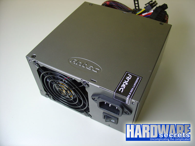
Figure 1: Antec NeoPower 550.
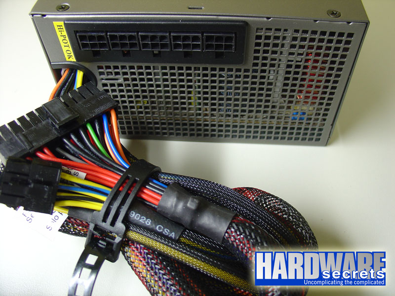
Figure 2: Antec NeoPower 550.
This power supply has active PFC (Power Factor Correction), which provides a better usage of the power grid and allows this power supply to be comply with the European law, making Antec able to sell it in that continent (you can read more about PFC on our Power Supply Tutorial). In Figure 1, you can see that this power supply doesn’t have an 110V/220V switch, feature available on power supplies with active PFC.
On the cooling side, this power supply uses the standard cooling system available since the beginning of times: an 80 mm fan on the back of the unit pulling hot air from inside the PC case to the outside. The front side of the unit – which will be located inside the PC case and where the hot air will enter – uses a huge mesh, allowing a terrific airflow. Low-end power supplies usually have only a few openings, providing a low airflow. You can see this mesh in Figure 2.
In Figure 2 you can also see that this power supply uses a modular cabling system for the peripheral cables, which is fantastic for two reasons. First, you need only to attach the peripheral cables you will really need, so you won’t have loose cables inside your PC, providing a better inner airflow. Second, if in the future you need different peripheral cables you can get them with the manufacturer instead of having to buy a new power supply just because your unit doesn’t have the cables you need. A plastic sleeving also protects the peripheral cables, helping organizing the cables inside the PC, providing a better inner airflow thus preventing it from overheating due to loose wires and cables blocking the airflow.
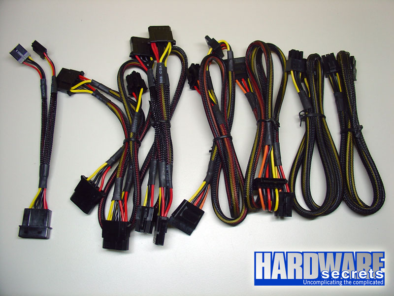
Figure 3: Peripheral cables.
NeoPower 550 comes with two auxiliary PCI Express cables, two peripheral cables with three peripheral power connectors each, two Serial ATA power cables with two Serial ATA power connectors each, and a floppy disk drive adapter, which converts a peripheral power connector into two floppy disk drive power connectors.
The main power cables – which don’t use the modular cabling system – include the main motherboard cable with one 20/24-pin motherboard connector, one ATX12V motherboard connector and one EPS12V motherboard connector. This power supply uses a very simple mechanism to convert its 24-pin main power connector into a 20-pin one, see Figure 4.
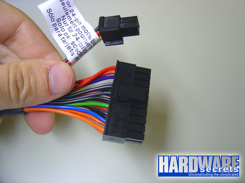
Figure 4: Its 24-pin power connector can be easily transformed into a 20-pin one.
[nextpage title=”Some Aesthetic Flaws”]
We found some finishing details that could be worked out by Antec. Even though we posted “flaw” on the subtitle, what we are describing now is not really a problem but just a matter of aesthetics.
First, the plastic seeving doesn’t come from inside the power supply, as you can see in Figure 5. So the wires from the motherboard power connectors are exposed while they exit the power supply housing.
Figure 5: The plastic sleeving doesn’t come from inside the power supply.
By the same token the plastic sleeving doesn’t go all the way to the output connectors, see Figure 6.
Figure 6: The plastic sleeving doesn’t go all the way to the end of the cable.
We decided to disassemble this power supply to take a look inside.
[nextpage title=”A Look Inside The NeoPower 550″]
We decided to disassemble this power supply to see if it internally is really different from generic power supplies. Please read our Anatomy of Switching Power Supplies tutorial to understand how a power supply works and to compare this power supply to a generic one.
In this page we will have an overal look, while in the next page we will discuss in details the quality and rating of the components used.
We can point out several differences between this power supply and a low-end (a.k.a. “generic”) one: the construction quality of the printed circuit board (PCB); the use of more components on the transient filtering stage; the active PFC circuitry; the use of a thermal sensor on the power diodes heatsink for controlling the fan speed and for shutting down the power supply in case of overheating; the power rating of all components; the design; etcetera.
In Figure 7 you can have an overall look this power supply from inside.
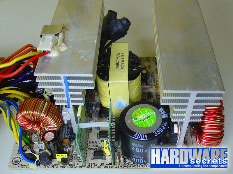
Figure 7: Inside Antec NeoPower 550.
In the next page we will have a more detailed discussion about the components used in the NeoPower 550.
[nextpage title=”Transient Filtering Stage”]
The first place we like to take a look when opening a power supply to have a hint about its quality is its filtering stage. On generic power supplies this stage has only one coil, two ceramic capacitors, one or two metalized polyester capacitors and, if we are lucky, one MOV (Metal-Oxide Varistor). This power supply from Antec uses one MOV (behind the ferrite coil on the right in Figure 9, so it couldn’t be shown), two ceramic capacitors, two
metalized polyester capacitor, three ferrite coils, plus a ferrite bead on the main power cord.
Also, the components from the first stage of the transient filter are usually soldered on the main power connector, but on this power supply they are located on a small printed circuit board attached to the main power connector, which is far better than having components directly soldered to the main power connector.
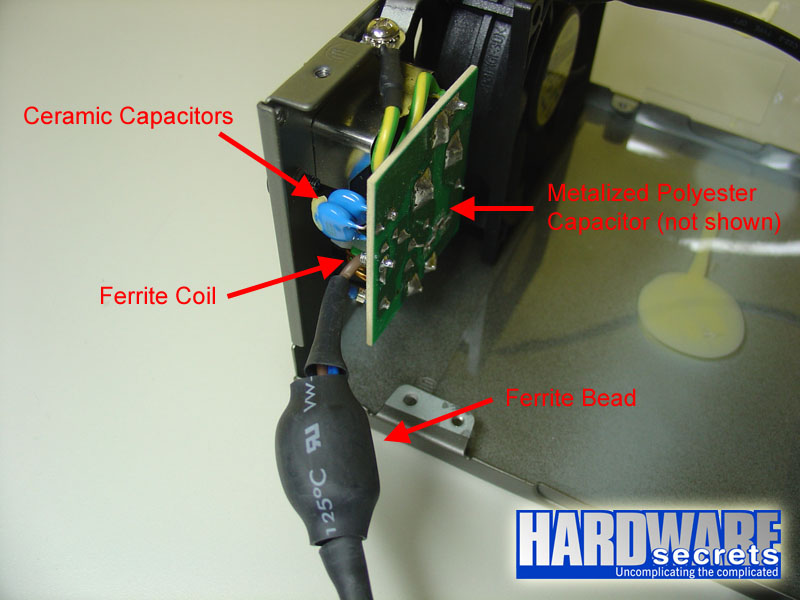
Figure 8: Transient filtering stage (part 1).
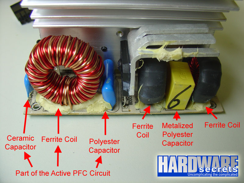
Figure 9: Transient filtering stage (part 2).
In Figure 9 you also see a ferrite coil, a ceramic capacitor and a polyester capacitor that are used on the active PFC circuit.
[nextpage title=”Primary Analysis”]
We were very curious to check what components were chosen for the power section of this power supply and also how they were set together, i.e., the design used. We were willing to see if the components could really deliver the power announced by Antec.
From all the specs provided on the databook of eachcomponent, we are more interested on the maximum continuous current parameter, given in ampères or amps for short. To find the maximum theoretical power capacity of the component in watts we need just to use the formula P = V x I, where P is power in watts, V is the voltage in volts and I is the current in ampères.
Keep in mind that this doesn’t mean that the power supply will deliver the maximum current rated for each component as the maximum power the power supply can deliver depends on the other components used – like the transformer, coils, the PCB layout and the wire gauge – not only on the specs of the main components we are going to analyze.
For a better understanding of what we are talking here, please read our Anatomy of Switching Power Supplies tutorial.
This power supply uses a GBU1006 rectifying bridge in its primary stage, which can deliver up to 10 A of continuous current. This component is clearly overspec’ed: at 115 V this unit would be able to pull up to 1,150 W from the power grid; assuming 80% efficiency, the bridge would allow this unit to deliver up to 920 W without burning this component. Of course we are only talking about this component and the real limit will depend on all other components from the power supply.
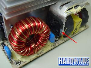
Figure 10: Rectifying bridge on this power supply.
On its primary stage, four power MOSFET transistors are used, two 20N60C3 for the active PFC circuit (20 A maximum at 110° C each) and two FQA18N50V2 (12.7 A maximum at 100° C each) for the switching section, which uses a two-transistor forward configuration. For a better understanding on the relationship between these transistors, we drew a simplified diagram of this section of the NeoPower 550 power supply, see Figure 11.

Figure 11: Simplified diagram of this power supply showing the location of the four MOSFET transistors.
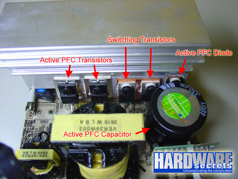
Figure 12: MOSFET transistors used on this power supply.
The primary is controlled by a CM6800 integrated circuit, which is an active PFC and PWM controller combo. It is located on a small printed circuit board shown in Figure 13.
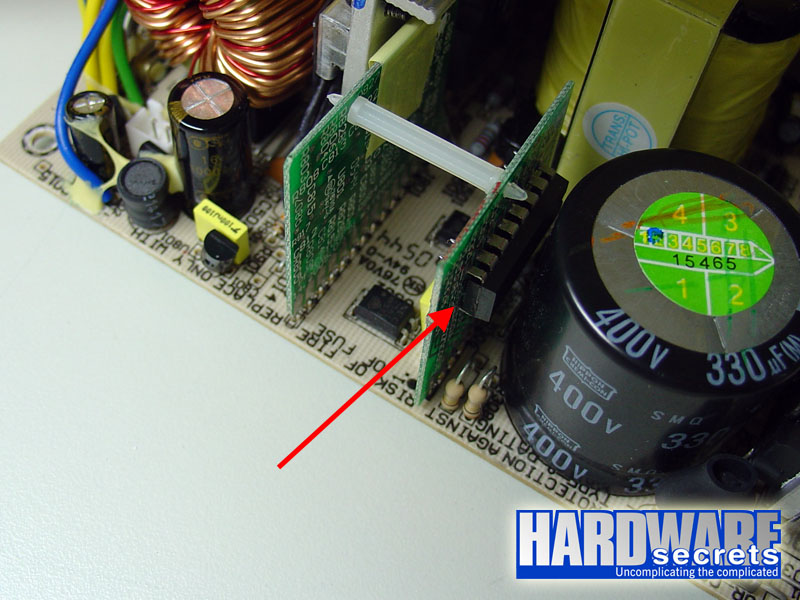
Figure 13: Active PFC and PWM controller integrated circuit.
[nextpage title=”Secondary Analysis”]
But we are really interested on the secondary part of the power supply.
Its +12 V output is produced by two MBR4060WT Schottky rectifiers installed in parallel, each one supporting up to 40 A continuous current (20 A each internal diode, measured at 108° C). The maximum theoretical current the +12 V line can deliver is given by the formula I / (1 – D), where D is the duty cycle used and I is the maximum current supported by the rectifying diode (which in this case is made by two 20 A diodes in parallel). Just as an exercise, we can assume a typical duty cycle of 30%. This would give us a maximum theoretical current of 57 A or 684 W for the +12 V output. The maximum current this line can really deliver will depend on other components, in particular the coil used.
Its +5 V output is produced by one STPS30L45CW Schottky rectifier, which can handle up to 30 A of continuous current (15 A each internal diode, measured at 135° C). The maximum theoretical current the +5 V line can deliver is given by the formula I / (1 – D), where D is the duty cycle used and I is the maximum current supported by the rectifying diode (which in this case is made by one 15 A diode). Just as an exercise, we can assume a typical duty cycle of 30%. This would give us a maximum theoretical current of 21 A or 107 W for the +5 V output. The maximum current this line can really deliver will depend on other components, in particular the coil used.
The rectifier used on the +3.3 V output is a STPS30L40CW, which can handle up to 30 A (15 A each internal diode, measured at 135° C). Using the same math as published above the +3.3 V output would be able to deliver 21 A or 71 W.
However, both +3.3 V and +5 V rectifiers are connected to the same transformer output, so the maximum combined current these two outputs can deliver will depend on the transformer.
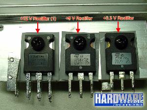
Figure 14: Rectifiers used on this power supply.
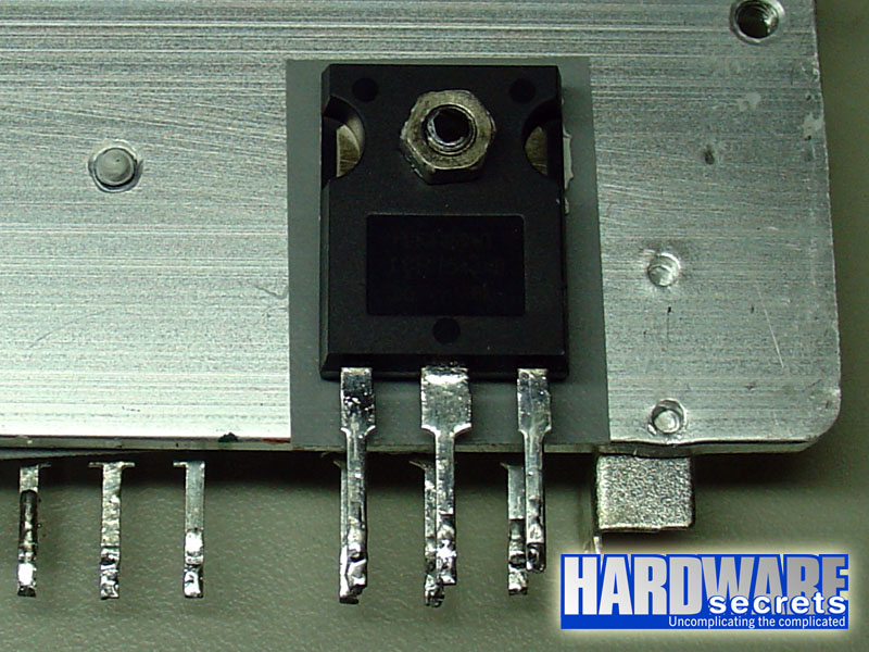
Figure 15: Second rectifier for the +12 V output.
This power supply also has a true temperature sensor attached to the heatsink used by the secondary rectifiers, in charge of controlling the fan speed according to the power supply temperature, which is a great feature to reduce noise, as the fan will rotate on its maximum speed only when needed.
Antec also chose to add a 7805 voltage regulator connecting the +12 V to the +5 V output, which is probably to simulate a load and allow the power supply to turn on.
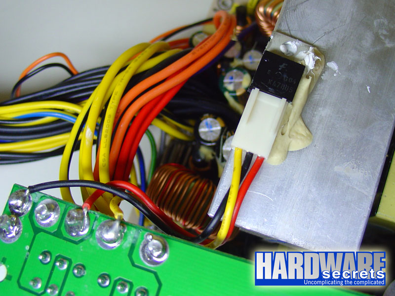
Figure 16: 7805 voltage regulator connected between the +12 V and +5 V outputs.
The electrolytic capacitor used on the active PFC circuit is from Japanese Chemi-Con, while all other electrolytic capacitors are from Taiwanese OST.
[nextpage title=”Power Distribution”]
In Figure 17, you can see NeoPower 550 label stating all its power specs.
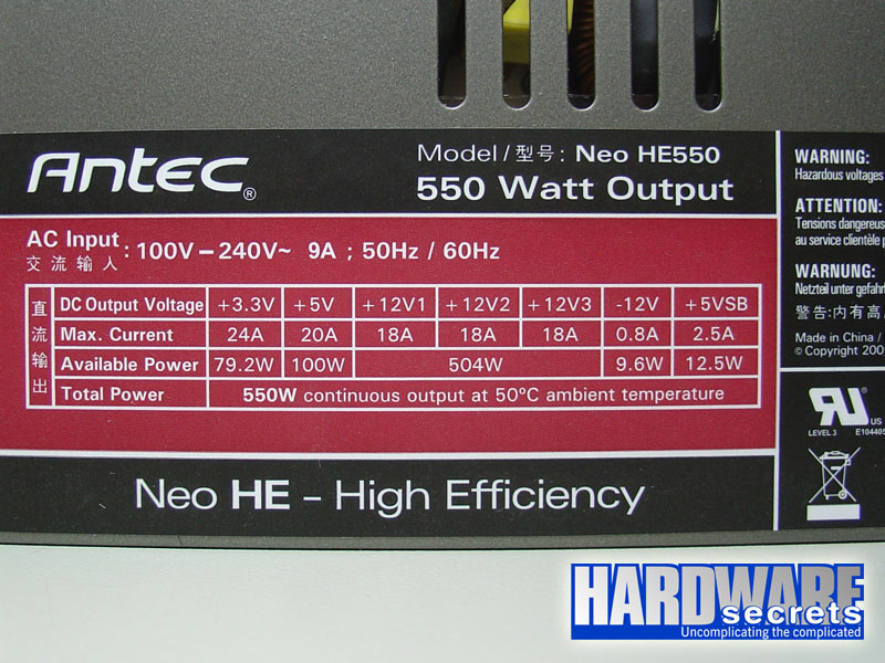
Figure 17: Power supply label.
As you can see on the label this power supply has three +12V rails. These rails are “virtual” as all of them are connected together to the single +12 V “real” rail coming from the +12 V rectifiers through a series of jumpers (“shunts”). You can see this on Figures 18 and 19.
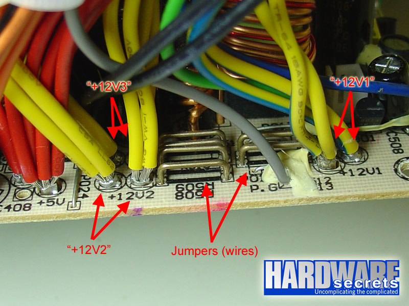
Figure 18: +12 V wires are separated into six wire groups and connected to the PCB as if there were three separated rails.
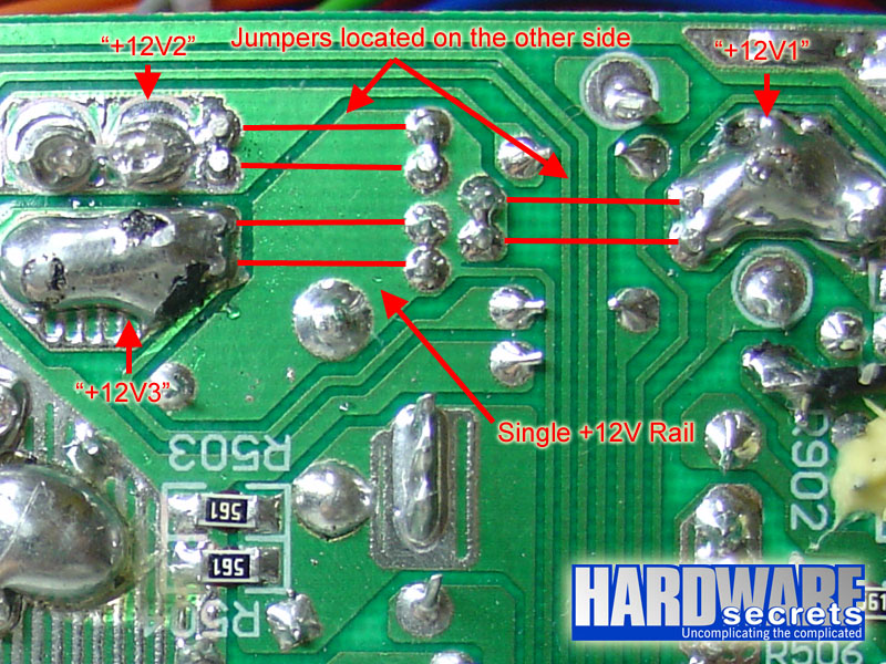
Figure 19: However they are connected together on the PCB.
Each virtual rail, however, has its own over current protection (OCP) and that is why they are listed as individual rails even though they are all connected to the same place inside the power supply. From what the label says the over current protection is configured to shut down the power supply if you pull more than 18 A in any of the three rails (usually the over current protection circuit is set with a value a little bit higher than what is written on the label). At least in theory, as during our tests we pulled a lot more than 18 A on +12V1 rail and the power supply didn’t shut down (but let’s not get ahead of ourselves; more about this in the next page).
On power supplies with multiple rails it is very important to see how the available connectors are distributed among the available rails. On NeoPower 550 Antec distributed the connectors like this:
- +12V1: ATX12V, half of EPS12V.
- +12V2: All plugs from the modular cabling system.
- +12V3: Motherboard main connector, half of EPS12V.
One curious thing is the fact that half of the EPS12V plug is connected to the +12V1 rail (yellow with blue stripe wire) and half to the +12V3 rail (yellow with black stripe wire), as you can see in Figure 20.
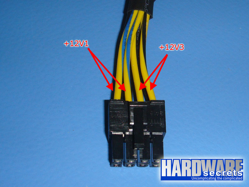
Figure 20: The EPS12V plug is connected to both +12V1 and +12V3 rails.
Putting all connectors from the modular cabling system on the same rail was something that we wouldn’t recommend because of the video card connectors (PCI Express auxiliary cables), which pull a lot of current (and thus power). This configuration, however, didn’t have any impact on the performance of this unit, as we will show in the next page.
Another curiosity is that the plugs from the modular system are connected to the +12V2 rail through two sets of two wires each. The first set is connected to the first two connectors and the second set is connected to the remaining connectors, as we clarify in Figure 21.
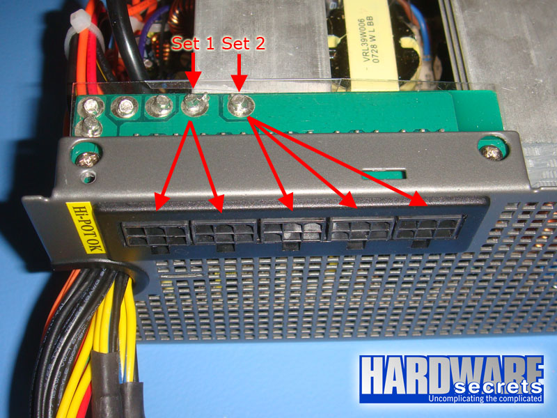
Figure 21: How the plugs from the modular system are connected to the +12V2 rail.
Because each wire has its own current limit (which is a physical limit) if you are not going to use all the cables from the modular system, which is more likely, you will have a better power/current distribution if you balance the two groups of connectors. For example, if you are going to use just two cables, attach the first one to the first plug and the second one to the last plug (instead of using the second plug).
[nextpage title=”Load Tests”]
We conducted several tests with this power supply, as described in the article Hardware Secrets Power Supply Test Methodology. All the tests described below were taken with a room temperature between 47° and 50° C. During our tests the power supply temperature was between 48° and 49° C.
First we tested this power supply with fiv different load patterns, trying to pull around 20%, 40%, 60%, 80%, and 100% of its labeled maximum capacity (actual percentage used listed under “% Max Load”), watching how the reviewed unit behaved under each load. In the table below we list the load patterns we used and the results for each load.
+12V2 is the second +12V input of our load tester and on this test it was connected to the power supply EPS12V connector. Keep in mind that power supply uses a multiple rail design with three virtual rails and these rails were divided between the +12V1 and +12V2 inputs from our load tester.
| Input | Test 1 | Test 2 | Test 3 | Test 4 | Test 5 |
| +12V1 |
4 A (48 W) |
8 A (96 W) |
12 A (144 W) |
16 A (192 W) |
20 A (240 W) |
| +12V2 |
4 A (48 W) |
8 A (96 W) |
12 A (144 W) |
16 A (192 W) |
20 A (240 W) |
| +5V |
1 A (5 W) |
2 A (10 W) |
4 A (20 W) |
5 A (25 W) |
6 A (30 W) |
| +3.3 V |
1 A (3.3 W) |
2 A (6.6 W) |
4 A (13.2 W) |
5 A (16.5 W) |
6 A (19.8 W) |
| +5VSB |
1 A (5 W) |
1 A (5 W) |
1.5 A (7.5 W) |
2 A (10 W) |
2.5 A (12.5 W) |
| -12 V |
0.5 A (6 W) |
0.5 A (6 W) |
0.5 A (6 W) |
0.5 A (6 W) |
0.8 A (9.6 W) |
| Total |
115 W |
220 W |
335 W |
442 W |
552 W |
| % Max Load |
21% |
40% |
61% |
80% |
100% |
| Result | Pass | Pass | Pass | Pass | Pass |
| Voltage Stability | Pass | Pass | Pass | Pass | Pass |
| Ripple and Noise | Pass | Pass | Pass | Pass | Pass |
| Efficiency | 86.5% | 88% | 87% | 85.5% | 83.3% |
As you can see this power supply could not only deliver its labeled power at 50° C but could keep an efficiency of at least 83%, going as high as 88% when we were pulling around 220 W or 40% of its capacity. As for noise, the maximum level we’ve seen was of 44 mV peak-to-peak on +12V2 input during test number five, which is well below the 120 mV maximum allowed.
After being happy with these results we tried to pull even more power from NeoPower 550 and the good news is that we were able to do so, even with a room temperature of 50° C!
Below you can see the maximum amount of power we could extract from this unit keeping it working with its voltages and noise level within the proper working range. As we can see what we could do was to pull 8 amps more from the +12V1 input of our load tester. We tried other configurations (like trying to pull more from +5 V, +3.3 V and +12V2) but this was the one that provided the maximum load with the power supply working. Above that voltages weren’t within working range and ripple was through the roof.
| Input | Maximum |
| +12V1 | 28 A (336 W) |
| +12V2 | 20 A (240 W) |
| +5V | 6 A (30 W) |
| +3.3 V | 6 A (19.8 W) |
| +5VSB | 2.5 A (12.5 W) |
| -12 V | 0.8 A (9.6 W) |
| Total | 647.9 W |
| % Max Load | 117.80% |
| Efficiency | 81% |
Working at this spec, however, noise level at +12V2 input doubled, jumping to 80 mV. Even though this value is still inside working specs (120 mV) it is clear to us that this power supply wasn’t projected to work above 550 W. But, as we could see, this unit will work up to 650 W at 50° C just fine – which is outstanding.
We couldn’t pull more than that from our power supply, even when we tried to increase currents little-by-little starting from the above values with the power supply already on.
It seems, however, that this power supply doesn’t have over current (OCP) and over power (OPP) protections – at least with us this unit failed on these tests.
On power supplies with OPP when we try to turn it on with a load higher than then it is capable of handling, the power supply simply won’t turn on. Also if we start increasing power with the unit already on, it will shut down whenever it reaches a point it can’t work within its specs anymore.
NeoPower 550, however, didn’t turn off under these two circumstances. It kept turned on, but with voltages below working range (+12 V dropped to +7 V, for example) and ripple through the roof.
As for OCP we did a simple test. We connected the ATX12V connector from the power supply to the +12V2 input from the load tester. As we explained on last page, this plug is connected to the +12V1 rail and since we left the EPS12 plug unconnected this plug was the only thing connected to the +12V1 rail from the power supply. We turned on the load tester with our test number one and increased the current on ATX12V to 18 A, then to 20 A, then to 22 A, then to 24 A and the power supply didn’t shut down as it should (from the power supply label it should have shut down at 18 A or at a little bit above that).
This isn’t necessarily a bad thing. Probably we could only pull 650 W from this power supply because OCP and OPP weren’t in place.
A feature we could see in action was the fan speed changing depending on the power supply temperature. This feature is great because it reduced the noise produced by your power supply when you are not pulling a lot of power, as the fan will rotate at a lower speed.
[nextpage title=”Main Specifications”]
Antec NeoPower 550 power supply specs include:
- ATX12V 2.2
- Nominal labeled power: 550 W at 50° C.
- Measured maximum power: 650 W at 50° C.
- Nominal labeled efficiency: up to 85%.
- Measured efficiency: Between 83% and 88% at 115 V.
- Active PFC: Yes.
- Motherboard Connectors: 20/24-pin connector, ATX12V connector and EPS12V connector.
- Peripheral Connectors: Modular system allowing up to five cable groups to be connected. This power supply comes with the following cables: two auxiliary PCI Express cables, two peripheral cables with three peripheral power connectors each, two Serial ATA power cables with two Serial ATA power connectors each, and a floppy disk drive adapter, which converts a peripheral power connector into two floppy disk drive power connectors.
- Protections: short-circuit (SCP), under voltage (UVP), overload power (OPP), over current (OCP) and over voltage (OVP).
- Warranty: 5 years.
- More Information: https://www.antec.com
- Average price in the US*: USD 114.50.
* Researched at Shopping.com on the day we published this review.
[nextpage title=”Conclusions”]
This power supply is simply unbelievable: even though it is labeled as a 550 W unit it could deliver 650 W at 50° C. What an animal! Several power supplies on the market aren’t able to deliver its rated power under real-world conditions – namely a room temperature above 40° C – and this power supply could not only do that but deliver 100 W more power! Costing around USD
110 this product presents one of the best cost/benefit ratios on the market, as you will be paying for a 550 W unit but actually buying a 650 W unit. It deservers nothing less than our “Golden Award” seal.
During our tests it provided an efficiency between 83% and 88%, which is outstanding, as it will allow you to save some money on your electricity bill compared to units with efficiency below 80%.
Feature-wise this power supply uses a modular cabling system. We like systems like this as you can remove all the cables you are not going to use, helping the computer internal airflow. Even though it uses a traditional 80 mm fan on its rear, this fan was very quiet when the power supply was working at a light load. As we mentioned, the power supply fan speed changes depending on the unit’s internal temperature.
Another great feature about this power supply is its warranty: 5 years. This only shows the commitment of the manufacturer that you won’t have any problem with this unit.
With two auxiliary PCI Express power connectors for your SLI or CrossFire system and one EPS12V connector, which is used by some high-end motherboards, this power supply should be enough even for some high-end users. Of course If you go with SLI or CrossFire with the most high-end video cards available today you will need a power supply with a higher wattage, like 850 W.


Leave a Reply