[nextpage title=”Introduction”]
When we saw this ultra low-end iMicro PS-IM400WH power supply being sold for only USD 12, we couldn’t help ourselves. We had to buy it and test it using the same standards we use for evaluating more expensive units. So, how will this bargain unit perform? Is it safe to use it? Let’s check it out.
Figure 1: iMicro PS-IM400WH power supply
Figure 2: iMicro PS-IM400WH power supply
The iMicro PS-IM400WH follows the traditional ATX design, being 5.5” (140 mm) deep, using an 80 mm sleeve bearing fan on its rear side, and based on the obsolete half-bridge topology.
Being an ultra low-end product, it doesn’t have active PFC circuit, modular cabling system, or sleeves protecting the cables. All wires are 20 AWG, which are thinner than the minimum recommended (18 AWG). The cables available are:
- Main motherboard cable with a 20/24-pin connector, 12” (30 cm) long
- One cable with one ATX12V connector, 13.4” (34 cm) long
- One cable with one SATA power connector, 12” (30 cm) long
- One cable with two standard peripheral power connectors, 12.2” (31 cm) to the first connector, 5.9” (15 cm) between connectors
- One cable with two standard peripheral power connectors and one floppy disk drive power connector, 12.2” (31 cm) to the first connector, 5.9” (15 cm) between connectors
The number of connectors is ridiculous, with only one SATA connector and no video card power connector. This configuration is not satisfactory even if you are building an ultra entry-level PC, because you will need at least two SATA power connectors, one for your optical drive and one for your hard drive. The cables are also too short.
Let’s now take an in-depth look inside this power supply.
[nextpage title=”A Look Inside The iMicro PS-IM400WH”]
We decided to disassemble this power supply to see what it looks like inside, how it is designed, and what components are used. Please read our Anatomy of Switching Power Supplies tutorial to understand how a power supply works and to compare this power supply to others.
This page will be an overview, and then in the following pages we will discuss in detail the quality and ratings of the components used.
Figure 7: Printed circuit board
[nextpage title=”Transient Filtering Stage”]
As we have mentioned in other articles and reviews, the first place we look when opening a power supply for a hint about its quality, is its filtering stage. The recommended components for this stage are two ferrite coils, two ceramic capacitors (Y capacitors, usually blue), one metalized polyester capacitor (X capacitor), and one MOV (Metal-Oxide Varistor). Very low-end power supplies use fewer components, usually removing the MOV and the first coil.
In order to cut costs, the manufacturer added only two Y capacitors in this stage. We’d like to remember you that the transient filtering stage is used not only to “clean” the electricity coming from the wall, but it is also in charge of preventing the interference created by switching section of the power supply from entering the power grid.
Figure 8: Transient filtering stage
In the next page we will have a more detailed discussion about the components used in the iMicro PS-IM400WH.
[nextpage title=”Primary Analysis”]
On this page we will take an in-depth look at the primary stage of iMicro PS-IM400WH. For a better understanding, please read our Anatomy of Switching Power Supplies tutorial.
Instead of using a ready-made rectifying bridge, the manufacturer decided to create the bridge using four discrete diodes. But instead of using four identical diodes, the manufacturer used two 1N5408 (3 A at 75° C) and two RL207 (2 A at 75° C) diodes. Because they are different, we have to consider the lower limit, which is 2 A, for our calculations. The 2 A diodes make this power supply to be able to pull only up to 230 W from a 115 V power grid. Assuming 80% efficiency, these diodes would allow this unit to deliver only up to 184 W. Here we can clearly see that this unit can’t be a 400 W power supply.
In the switching section this power supply uses two 13007 power NPN transistors, connected using the obsolete half-bridge topology. Each one supports up to 8 A at 25° C (unfortunately the manufacturer doesn’t say the current limit at higher temperatures). These transistors are very popular among ultra low-end products.
Figure 10: Switching transistors
The switching transistors are controlled by a TL494 PWM controller, which is physically located in the secondary.
Now let’s take a look at the secondary of this power supply.
[nextpage title=”Secondary Analysis”]
This power supply uses three rectifiers in its secondary.
The maximum theoretical current each line can deliver is given by the formula I / (1 – D), where D is the duty cycle used and I is the maximum current supported by the rectifying diode. Since this unit is based on the half-bridge topology, the duty cycle used is of 50%.
The +12 V output is produced by one F16C20C rectifier, which supports up to 16 A (8 A per internal diode at 125° C, maximum voltage drop of 1.30 V, which is extremely high). This translates into a maximum theoretical current of 16 A or 192 W for the +12 V output. It is important to understand that this rectifier isn’t a “Schottky” model, but rather a “Fast” model, which presents a higher voltage drop (translation: lower efficiency).
The +5 V output is produced by one S20C45C Schottky rectifier, which supports up to 20 A (10 A per internal diode at 125° C, maximum voltage drop of 0.65 V). This translates into a maximum theoretical current of 20 A or 100 W for the +5 V output.
The +3.3 V output is produced by one HBR2045 Schottky rectifier, which supports up to 20 A (10 A per internal diode at 150° C, maximum voltage drop of 0.7 V). This translates into a maximum theoretical current of 20 A or 66 W for the +3.3 V output.
Of course these are theoretical numbers, and the real limits will depend on other components as well.
It is interesting to note how the +5 V and +3.3 V rectifiers are “stronger” than the +12 V rectifier. This is a typical scenario of 10 years ago, but nowadays most of the current/power pulled by the computer is concentrated on the +12 V rail (because of the CPU and the video cards).
Figure 12: +3.3 V, +12 V and +5 V rectifiers
One thing that caught our attention was the absence of filtering coils in the secondary of this power supply. Without these components, this power supply is prone to deliver high noise and ripple levels in its outputs.
Figure 13: Absence of filtering coils in the secondary
The power good signal and the available protections are implemented using an AS339 integrated circuit, which has four voltage comparators inside.
The electrolytic capacitors in the voltage doubler circuit are from LCZ, while the electrolytic capacitors in the secondary are from BH and Fcon.
[nextpage title=”Power Distribution”]
In Figure 15, you can see the power supply label containing all the power specs.
Let’s now see how much power this power supply can deliver.
[nextpage title=”Load Tests”]
We conducted several tests with this power supply, as described in the article Hardware Secrets Power Supply Test Methodology.
Because we had no clue as to the real wattage of this power supply, we tested it differently. Starting from 85 W, we increased load little by little until we could see the maximum amount of power we could extract from the reviewed unit.
If you add all the power listed for each test, you may find a different value than what is posted under “Total” below. Since each output can vary slightly (e.g., the +5 V output working at +5.10 V), the actual total amount of power being delivered is slightly different than the calculated value. In the “Total” row, we are using the real amount of power being delivered, as measured by our load tester.
The +12VA and +12VB inputs listed below are the two +12 V independent inputs from our load tester. During our tests, both were connected to the power supply’s single +12 V rail.
Input | Test 1 | Test 2 | Test 3 | Test 4 | Test 5 |
+12VA | 3 A (36 W) | 3.5 A (42 W) | 4.5 A (54 W) | 5.5 A (66 W) | 6.25 A (75 W) |
+12VB | 2.5 A (30 W) | 3.25 A (39 W) | 4 A (48 W) | 5 A (60 W) | 6 A (72 W) |
+5V | 1 A (5 W) | 1 A (5 W) | 1.5 A (7.5 A) | 1.5 A (7.5 A) | 2 A (10 W) |
+3.3 V | 1 A (5 W) | 1 A (5 W) | 1.5 A (4.95 W) | 1.5 A (4.95 W) | 2 A (6.6 W) |
+5VSB | 1 A (5 W) | 1 A (5 W) | 1 A (5 W) | 1 A (5 W) | 1 A (5 W) |
-12 V | 0.5 A (6 W) | 0.5 A (6 W) | 0.5 A (6 W) | 0.5 A (6 W) | 0.5 A (6 W) |
Total | 78.2 W | 98.5 W | 128.6 W | 145.5 W | 169.5 W |
% Max Load | 19.6% | 24.6% | 32.2% | 36.4% | 42.4% |
Room Temp. | 41.3° C | 41.5° C | 41.9° C | 42.7° C | 43.4° C |
PSU Temp. | 42.7° C | 43.5° C | 44.2° C | 44.4° C | 44.8° C |
Voltage Regulation | Pass | Pass | Pass | Pass | Pass |
Ripple and Noise | Fail on +3.3 V | Fail on +3.3 V | Fail on +3.3 V | Fail on +3.3 V and -12 V | Fail on +3.3 V and -12 V |
AC Power | 102.1 W | 126.8 W | 164.7 W | 186.6 W | 218.6 W |
Efficiency | 76.6% | 77.7% | 78.1% | 78.0% | 77.5% |
AC Voltage | 110.1 V | 109.9 V | 110.2 V | 110.5 V | 110.4 V |
Power Factor | 0.647 | 0.653 | 0.655 | 0.650 | 0.650 |
Fina l Result |
Fail | Fail | Fail | Fail | Fail |
Input | Test 6 | Test 7 | Test 8 | Test 9 | Test 10 |
+12VA | 7.5 A (90 W) | 8.25 A (99 W) | 9.25 A (111 W) | 10 A (120 W) | 11 A (132 W) |
+12VB | 7 A (84 W) | 8 A (96 W) | 9 A (108 W) | 10 A (120 W) | 11 A (132 W) |
+5V | 2 A (10 W) | 2.5 A (12.5 W) | 2.5 A (12.5 W) | 3 A (15 W) | 3 A (15 W) |
+3.3 V | 2 A (6.6 W) | 2.5 A (8.25 W) | 2.5 A (8.25 W) | 3 A (9.9 W) | 3 A (9.9 W) |
+5VSB | 1 A (5 W) | 1 A (5 W) | 1 A (5 W) | 1 A (5 W) | 1 A (5 W) |
-12 V | 0.5 A (6 W) | 0.5 A (6 W) | 0.5 A (6 W) | 0.5 A (6 W) | 0.5 A (6 W) |
Total | 194.3 W | 217.5 W | 238.2 W | 260.4 W | 288.1 W |
% Max Load | 48.6% | 54.4% | 59.6% | 65.1% | 72.0% |
Room Temp. | 43.3° C | 45.0° C | 47.1° C | 49.0° C | 42.2° C |
PSU Temp. | 44.8° C | 46.0° C | 47.8° C | 49.6° C | 48.5° C |
Voltage Regulation | Pass | Pass | Fail on +12 V | Fail on +12 V | Fail on +12 V |
Ripple and Noise | Fail on +3.3 V and -12 V | Fail on +5 V, +3.3 V, and -12 V | Fail on +5 V, +3.3 V, and -12 V | Fail on +12V, +5 V, +3.3 V, and -12 V | Fail on +12V, +5 V, +3.3 V, and -12 V |
AC Power | 253.2 W | 287.3 W | 320.5 W | 358.2 W | 395.0 W |
Efficiency | 76.7% | 75.7% | 74.3% | 72.7% | 72.9% |
AC Voltage | 109.8 V | 109.0 V | 108.1 V | 107.6 V | 106.5 V |
Power Factor | 0.647 | 0.645 | 0.645 | 0.652 | 0.653 |
Final Result | Fail | Fail | Fail | Fail | Fail |
The iMicro PS-IM400WH isn’t a 400 W, as we suspected. In our tests it could deliver only up to 288 W. Above that, the power supply shuts down (at least it won’t burn or explode).
But carrying a fake wattage is the smallest of the problems presented by this power supply. It failed all our tests. The +12 V outputs presented voltages outside the proper range starting at 238 W, and because it lacks coils in its filtering stage, ripple and noise were always above the maximum allowed at the +3.3 V output during all tests. The -12 V output had noise and ripple levels above the maximum allowed starting at 145 W, the +5 V output presented noise above specs starting at 217 W, and the +12 V output presented noise above specs starting at 260 W.
During our test 10 noise level at +12 V output was at 131 mV, at +5 V output was at 58.8 mV, at +3.3 V output was at 57.2 mV, and at -12 V was at 185.4 mV.
Efficiency was always below 80%, between 72.9% and 78.1%.
[nextpage title=”Main Specifications”]
The specs of the iMicro PS-IM400WH include:
- Nominal labeled power: 400 W
- Measured maximum power: 288 W at 42.2° C ambient
- Labeled efficiency: Above 68% at full load at 115 V
- Measured efficiency: Between 72.9% and 78.1% at 115 V (nominal, see complete results for actual voltage)
- Active PFC: No
- Modular Cabling System: No
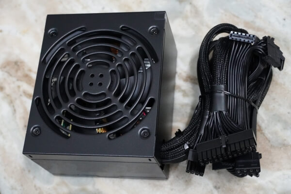
- Motherboard Power Connectors: One 20/24-pin connector and one ATX12V connector
- Video Card Power Connectors: None
- SATA Power Connectors: One
- Peripheral Power Connectors: Four on two cables
- Floppy Disk Drive Power Connectors: One
- Protections: Information not available
- Warranty: Information not available
- More Information: https://www.imicro.com
- Average price in the US*: USD 12.00
* Researched at Google Shopping on the day we published this review.
[nextpage title=”Conclusions”]
The iMicro PS-IM400WH is a typical ultra low-end power supply that must be avoided at all cost. Using this kind of bargain power supply will give you lots of headache.
This “400 W” unit can only deliver around 280 W, with low efficiency, and these are not even the worse problems of it.
The problem with ultra low-end power supplies, and the iMicro PS-IM400WH is no exception, is that their voltages get easily outside the proper working range, and the noise and ripple levels are always above the maximum allowed. These two problems will, in the best case scenario, make your computer to work unstable (i.e., presenting random problems), and, in the worst case scenario, overload and even burn components from your PC.
In summary: stay away!
Leave a Reply