Akasa Essential Power 300 W Power Supply Review
Primary Analysis
Contents
On this page we will take an in-depth look at the primary stage of the Akasa Essential Power 300 W. For a better understanding, please read our Anatomy of Switching Power Supplies tutorial.
This power supply uses one GBU605 rectifying bridge, which supports up to 6 A at 100° C if a heatsink is used, which fortunately is the case. Therefore, this unit would be able to pull up to 690 W from a 115 V power grid; assuming 80% efficiency, the bridge would allow this unit to deliver up to 552 W without burning itself out. Of course we are only talking about this component and the real limit will depend on all other components from the power supply.
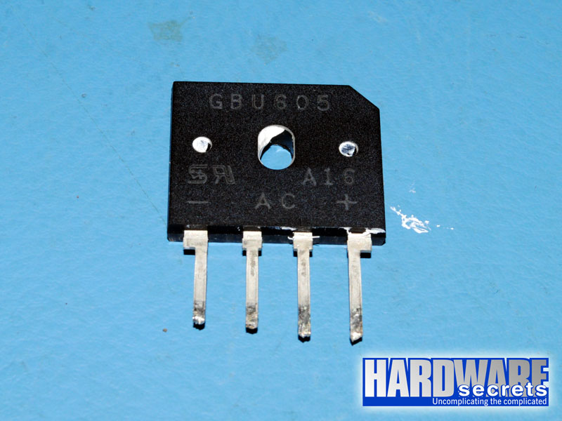 Figure 10: Rectifying bridge
The active PFC circuit uses only one transistor, an SPW16N50C3, capable of delivering up to 16 A at 25° C or up to 10 A at 100° C (note the difference temperature makes) in continuous mode, or up to 48 A in pulse mode at 25° C. This transistor presents a 280 mΩ resistance when turned on, a characteristic called RDS(on). The lower this number the better, meaning that the transistor will waste less power and the power supply will achieve higher efficiency.
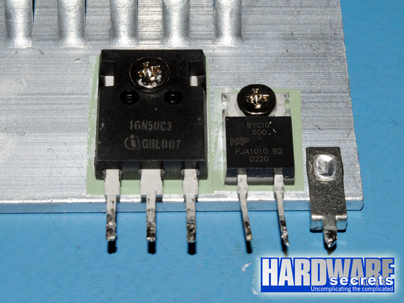 Figure 11: Active PFC transistor and diode
The electrolytic capacitor in charge of filtering the output of the active PFC circuit is manufactured by Teapo and labeled at 105° C.
The Akasa Essential Power 300 W uses the two-transistor forward configuration, using two 2SK4106 MOSFETs, each one supporting up to 12 A at 25° C in continuous mode (unfortunately the manufacturer doesn’t say the limit at 100° C) or up to 48 A at 25° C in pulse mode, with an RDS(on) of 400 mΩ.
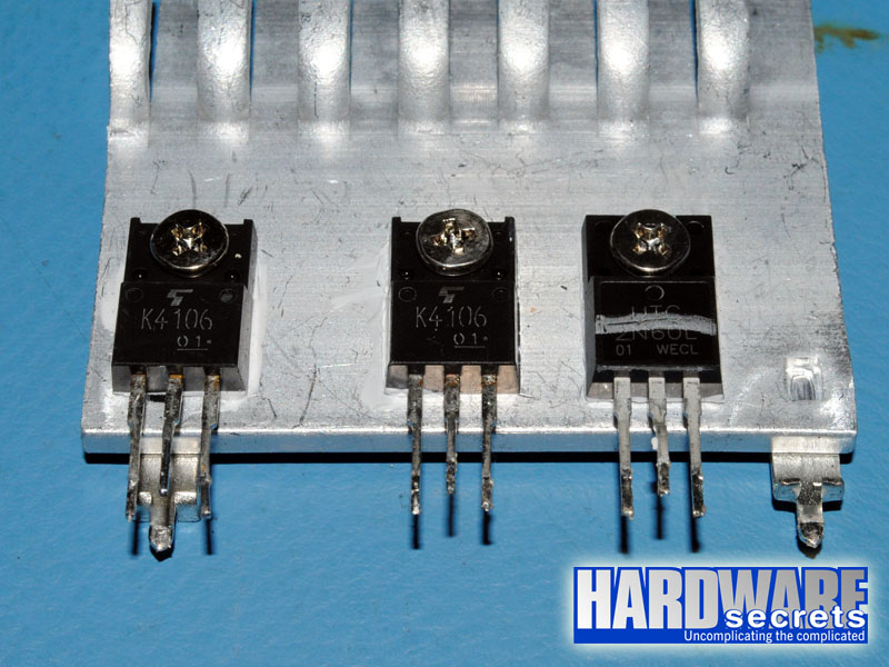 Figure 12: Switching transistors
The primary is controlled by a CM6805 active PFC/PWM combo controller.
 Figure 13: Active PFC/PWM controller
Let’s now take a look at the secondary from this power supply.