Borneo Schematic and Hardware Solution: Guide to Mobile Motherboard Repair
At a Glance
- Core Subject: Utilizing advanced PCB layout software for micro-soldering and smartphone logic board diagnostics.
- Primary Utility: Eliminating diagnostic guesswork through side-by-side schematics, bitmaps, and hardware jumper guides.
- Target Audience: Professional mobile repair technicians, independent shop owners, and advanced hardware engineers.
Navigating complex smartphone circuit boards requires far more than basic soldering tools and steady hands. Modern multi-layer logic boards pack thousands of microscopic components into tight spaces, making manual trace tracing nearly impossible under a microscope alone. This guide breaks down how digital diagnostic databases streamline repairs, reduce troubleshooting hours, and protect sensitive integrated circuits from thermal damage during complex reballing tasks.
Why Advanced Diagnostic Layouts Matter for Modern Workshops
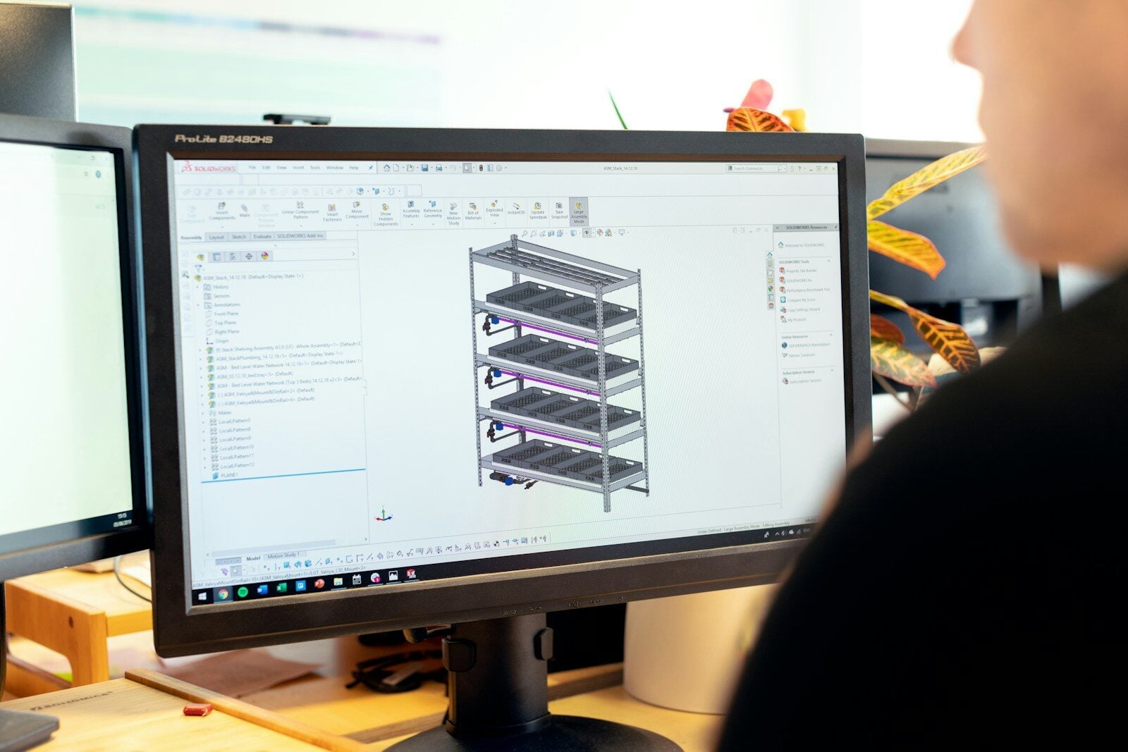
Finding a reliable borneo schematic and hardware solution fundamentally changes how repair technicians handle dead motherboards. Traditional PDF service manuals often lack real-time PCB bitmap alignment, forcing technicians to guess resistor values or trace hidden inner-layer lines manually. Modern software suites bridge this critical gap by pairing official electronic schematics with live layout viewers.
When a smartphone arrives with a shorted main power line, tracking the exact component drawing current saves hours of tedious multimeter testing. Having simultaneous access to physical board layouts and schematic symbols allows technicians to verify voltage drops instantly and execute precise repairs.
Core Features of Modern Repair Software
- Dual-View PCB Bitmaps: Compare a healthy board layout directly next to the schematic diagram to spot missing lines or torn solder pads.
- Hardware Solution Guides: Step-by-step visual references for common failure points, including charging errors, audio dropouts, and display backlight failure.
- Test Point Identification: Rapidly locate Emergency Download (EDL) points and debug pads for software recovery and bootloader unbricking.
Step-by-Step Diagnostic Workflow for Dead Boards
- Verify Current Draw: Connect the bare logic board to a DC power supply to observe initial amp spikes before pressing the power button.
- Consult the Layout Database: Open the specific device layout to find the primary line associated with the abnormal current draw.
- Isolate the Short: Use rosin smoke or a thermal camera to detect components heating up on the matched bitmap section.
- Perform Component Intervention: Shield surrounding sensitive integrated circuits with heat-resistant tape before lifting or replacing the shorted capacitor or power management IC.
Quick Comparison: Traditional Manuals vs. Modern Diagnostic Platforms
| Feature | Traditional PDF Manuals | Modern Visual Repair Toolsets |
| Trace Tracking | Manual page-flipping; difficult to follow inner layers | Interactive point-to-point net highlighting |
| Bitmap Integration | Rarely available or low resolution | Side-by-side physical board representation |
| Update Frequency | Static documents released once per model | Frequent cloud updates covering newly released devices |
| Hardware Solutions | Generic block diagrams | Specific jumperways and repair snapshots |
Practical Examples and Common Mistakes
A frequent error during logic board repair is applying excessive hot air temperature when dealing with underfilled integrated circuits. Technicians often rush the pre-heating stage, causing board delamination or lifting fragile pads beneath the baseband processor.
Another common mistake involves ignoring diode mode readings. Before injecting voltage into a suspected line, checking the reverse bias value against a known good reference layout prevents secondary damage to surrounding processor lines and power rails.
Pros and Cons of Digital Repair Intelligence Suites
- Pros:
- Massive time savings on complex diagnostic jobs and dead short isolation.
- Clear visual maps for jumper wires on torn or ripped solder pads.
- Regular cloud updates covering global smartphone releases.
- Cons:
- Requires an active paid subscription or periodic token renewal.
- Demands a stable internet connection for database authentication.
- Windows-exclusive architecture requires compatible PC workstation setups.
Integrating structured layout analysis into daily bench operations minimizes downtime and maximizes success rates on difficult micro-soldering repairs.