
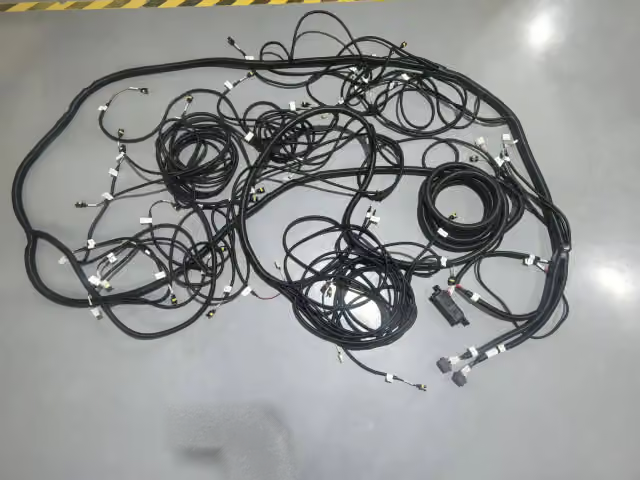
Robotics Cable Assemblies: Specifying for Flex, Torsion and Signal Integrity
A robot cable needs to keep working while the machine moves. A cable that feels flexible in your hand may still be unsuitable for repeated bending or twisting. It also has to carry power and signals without movement disrupting the connection.
When specifying robotics cable assemblies, describe the installed motion before choosing a cable. Show what happens between the cabinet, robot joints and end tool during a complete operating sequence.
Separate bending from twisting
Bending changes the cable’s curve. A cable carrier, often called a drag chain, typically guides cables through a repeated bend as the machine travels. Torsion means twisting the cable around its length, which can happen as a robot joint rotates. Some routes involve both.
These movements put different demands on the cable. A cable selected for repeated bending is not automatically suitable for repeated twisting. Likewise, being easy to bend during installation does not establish how long it will last in service.
Describe where each movement occurs. For a twisting section, include the rotation in each direction and the length of cable over which the twist is spread. For a bending section, show the tightest curve during operation. Bend radius describes how tight that curve is: a smaller radius means a tighter bend.
Use the requirements for the exact cable and motion type. A radius allowed for a fixed installation should not be treated as permission for continuous movement.
Show the route through the full movement
A drawing of the robot at rest can hide a cable that becomes tight, rubs a bracket or folds sharply at another position. Share the full travel range, operating speed and frequency of movement, along with routing drawings or a video of the proposed sequence.
Include the attachment points, moving cable lengths and nearby surfaces. If the assembly has several branches, show where they separate and whether they move together. A branch serving an end tool may face different movement from a cable running along the arm.
The route also needs space for movement without snagging. Too little free length can pull on a connection; extra length needs somewhere controlled to go. Agree on the installed layout rather than leaving the installer to decide where to put the slack.
Temperature, cleaning fluids and abrasion belong in this discussion too. Cable selection needs to account for the environment in which the movement takes place, not just the motion on a clean test bench.
Protect the connections without creating a new stress point
Strain relief supports the cable so pulling and movement do not act directly on its electrical terminations. Specify where the assembly is clamped and where it becomes free to move. The transition needs review because it can become a repeated bending point.
A shield connection and mechanical support perform different jobs. The shield helps control electrical interference; its connection should not be assumed to provide adequate strain relief. Clamps should also avoid crushing the cable.
Check connector access, branch exits and the cable’s path near the end tool. If tool changes require frequent disconnection, include that use in the requirements. An assembly that moves correctly but is difficult to disconnect or replace leaves a maintenance problem unresolved.
Treat signal integrity as an installed requirement
Signal integrity means that the receiving equipment gets a usable signal. Identify what each circuit carries, such as motor power, position feedback, sensor data or industrial Ethernet. Include the required interface, cable length, connector details and pin assignments.
A correctly wired connection is only part of the requirement. For PROFINET cabling, improper twisting or crushing can affect electrical performance. Use a cable rated for the intended torsion and keep the motion within its specified capability. Routing near power cables can also expose signals to interference.
Review power and signal routing with the equipment engineer. Specify the intended shield connections and follow the relevant equipment and network instructions rather than assuming one shielding arrangement suits every circuit. For PROFINET installations, the published installation guidelines address cabling and assembly as well as commissioning.
Plan to check communication or feedback while the robot moves and its drives operate. A check made only with the machine stationary may leave the operating conditions unexamined.
Qualify the assembly and plan for replacement
Before relying on a flex-cycle claim, check whether the test used the same type of motion and included the connectors, branches and clamps. A bending test alone does not show how the assembly handles twisting.
Agree on a representative motion test using the intended assembly and routing. Define the movement, environment, sample quantity and acceptable results before testing. The plan should address electrical function as well as physical damage, with checks during movement where the application requires them.
Keep the report tied to the tested drawing, cable part numbers and installation arrangement. Changes to the cable, connectors, clamps or route need review to decide whether further testing is necessary.
Finally, document how maintenance staff should inspect and replace the assembly. Include identification, attachment points and routing instructions so a replacement restores the approved layout.