ADATA BN-550 Power Supply Review
Secondary Analysis
Contents
The ADATA BN-550 has five Schottky rectifiers attached to its secondary heatsink.
The maximum theoretical current each line can deliver is given by the formula I / (1 – D) where D is the duty cycle used and I is the maximum current supported by the rectifying diode. As an exercise, we can assume a duty cycle of 30%.
The +12 V output uses two SBR30A50CT Schottky rectifiers (30 A, 15 A per internal diode at 125°, 0.55 V maximum voltage drop), giving us a maximum theoretical current of 43 A or 514 W for this output.
The +5 V output uses one PFR40V60CT Schottky rectifier (40 A, 20 A per internal diode at 120° C, 0.55 V maximum voltage drop), giving us a maximum theoretical current of 29 A or 143 W for this output.
The +3.3 V output uses two STPS30L45CT Schottky rectifiers (30 A, 15 A per internal diode at 135° C, 0.74 V maximum voltage drop), giving us a maximum theoretical current of 43 A or 141 W for this output.
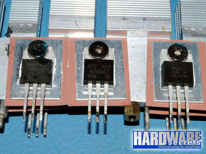 Figure 14: The +3.3 V, +5 V, and +12 V rectifiers
This power supply uses a PS223 monitoring integrated circuit, which supports over voltage (OVP), under voltage (UVP), over current (OCP), and over temperature (OTP) protections. This chip has four OCP channels, one for +3.3 V, one for +5 V, and two for +12 V, correctly matching the number of +12 V rails advertised by the power supply manufacturer (two).
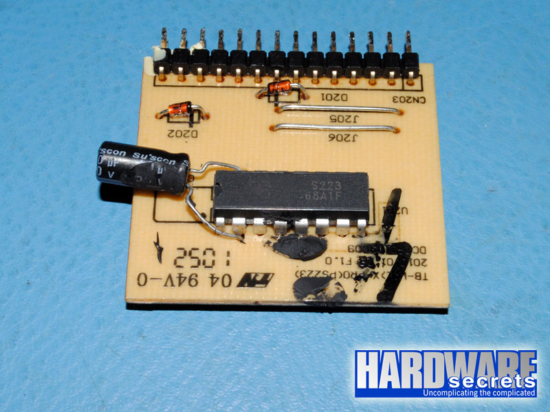 Figure 15: Monitoring circuit
The electrolytic capacitors available in the secondary are from Teapo and Su’scon, and labeled at 105° C.