3R System AK6-500M Power Supply Review
Secondary Analysis
Contents
The 3R System AK6-500M uses a regular design in its secondary, with Schottky rectifiers.
The maximum theoretical current that each line can deliver is given by the formula I / (1 – D) where D is the duty cycle used and I is the maximum current supported by the rectifying diode. As an exercise, we can assume a duty cycle of 30 percent.
The +12 V output uses four PFR20L60CT Schottky rectifiers, each one supporting up to 20 A (10 A per internal diode at 120° C with a 0.65 V maximum voltage drop). This gives us a maximum theoretical current of 57 A or 686 W for the +12 V output.
The +5 V output uses one PFR40L45PT Schottky rectifier, which supports up to 40 A (20 A per internal diode). Unfortunately, we couldn’t find its datasheet. This gives us a maximum theoretical current of 29 A or 143 W for the +5 V output.
The +3.3 V output uses two PFR30L45CT Schottky rectifiers, each one supporting up to 30 A (15 A per internal diode at 110° C with a 0.52 V maximum voltage drop). This gives us a maximum theoretical current of 43 A or 141 W for the +3.3 V output.
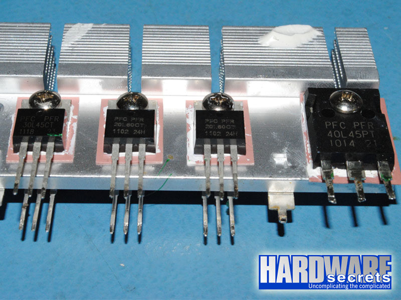 Figure 12: One of the +3.3 V rectifiers, two of the +12 V rectifiers, and the +5 V rectifier
This power supply uses a GR8323 monitoring integrated circuit, which supports over voltage (OVP), under voltage (UVP), and over current (OCP) protections. There are two +12 V over current channels, correctly matching the number of +12 V rails announced by the manufacturer.
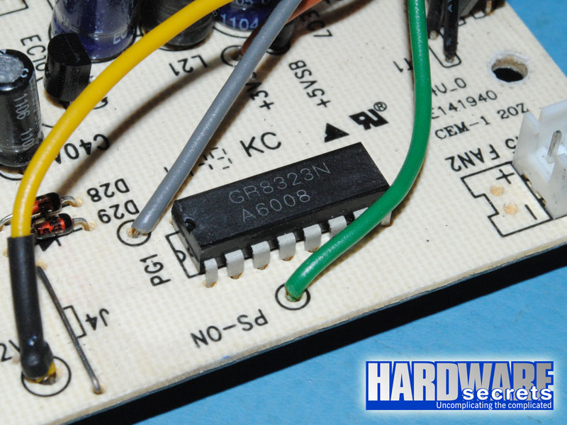 Figure 13: Monitoring circuit
The electrolytic capacitors that filter the outputs are from Asia’x and labeled at 105° C, as usual.