[nextpage title=”Introduction”]
Broadband routers are more popular each day and thanks to the launching of highly integrated controller chips today a broadband router needs only very few components to be manufactured – which is great to reduce the price of this device. Let’s see how a broadband router looks like inside.
Figure 1: Inside a broadband router.
As you can see in Figure 1, very few components are used. This happens because the big chip, the controller (a.k.a. router chip) is in charge of almost everything, basically combining router, switch and firewall functions. The other two smaller chips are memories, a RAM and a ROM. In Figure 2 you can find a summary of what is inside a broadband router.
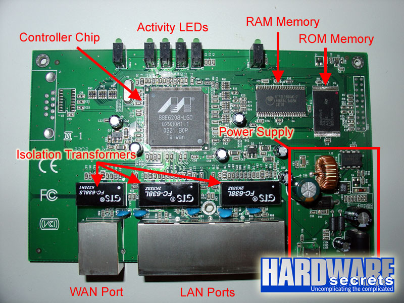
Figure 2: Anatomy of a broadband router.
In our router the big controller chip was a Marvell 88E6208, as you can see in Figure 3. As we already mentioned, this is the chip in charge of all router features (router, switch, firewall, etc). Some routers may have even less components if the main controller chip has embedded a RAM and/or a flash-ROM memory.
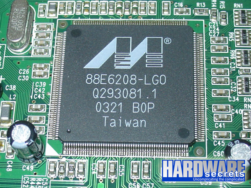
Figure 3: Controller chip.
On the next page we will talk about the other components.
[nextpage title=”Other Components”]
The RAM memory is used as buffer when you have computers transferring data at 100 Mbps to computers with 10 Mbps network cards. So a computer working at 100 Mbps doesn’t need to switch to 10 Mbps in order to transfer data to a slower computer, this RAM chip will allow it to maintain its maximum transfer rate, storing the data that is coming from the 100 Mbps connection temporarily there, and then the router will transferring the contents of this memory to the computer connected at 10 Mbps.
Our router used a 64-Mbit RAM memory chip (UT52L1664MC-7), i.e., it had an 8 MB buffer (64 Mbits / 8 = 8 MB).
Figure 4: RAM memory (buffer).
The ROM memory is usually a flash-ROM chip and stores the program that tells the controller how to work, a.k.a. firmware. It also stores the router configuration utility, which is usually accessed by opening a web browser and pointing to the router’s IP address – https://192.168.0.1 and https://192.168.1.1 are common values. Think of the router ROM memory as the router’s BIOS. Usually you are able to upgrade this firmware, if you’d like to, through the router configuration utility.
Our router used an 8-Mbit flash-ROM memory (M29W800DB), which equals to 1 MB (8 Mbits / 8 = 1 MB).
You can also see some components that belong to the router power supply section. You may think that the external power supply that comes with the router is in charge of delivering the required voltage for the operation of the router, but this isn’t entirely true. The external power supply only does half the job. The other half is done internally, basically reducing the voltage provided by the external power supply to the voltage required by the chips and regulating it – usually the voltage provided by cheap external power supplies isn’t regulated, so the regulation stage is inside the device to which it is connected to.
Figure 6: Voltage regulation section.
You can also see some big black components. They are isolation transformers, i.e., they work isolating the circuits connected to the RJ45 connectors (the network cards) from the router circuit. Isolation transformers are also known as 1:1 transformers.
Figure 7: Isolation transformers.
On routers with wireless capability you may also find an extra chip in charge of the wireless connectivity.
Leave a Reply