• Skip to primary navigation
  • Skip to main content
  • Skip to primary sidebar
  • Skip to footer
Hardware Secrets

Hardware Secrets

Uncomplicating the complicated

  • Case
  • Cooling
  • Memory
  • Mobile
    • Laptops
    • Smartphones
    • Tablets
  • Motherboard
  • Networking
  • Other
    • Audio
    • Cameras
    • Consumer Electronics
    • Desktops
    • Museum
    • Software
    • Tradeshows & Events
  • Peripherals
    • Headset
    • Keyboard
    • Mouse
    • Printers
  • Power
  • Storage
Home » ASUS P8P67 PRO Motherboard

ASUS P8P67 PRO Motherboard

[nextpage title=”Introduction”]

Even though the Intel Z68 chipset is out there, motherboards based on the Intel P67 continue to be attractive options for systems based on Intel socket LGA1155 CPUs. In fact, according to ASUS, the sales of P67-based motherboards are still outperforming those of Z68-based products. ASUS offers a wide range of motherboards based on this chipset, and today we are going to take a look at the P8P67 PRO model, which is a top mid-range model (or entry high-end model, depending on your point of view).

With eight different P8P67 models out there, you must be wondering what the differences between them are. To help you out, we compiled a table showing the main differences between the ASUS P8P67 models. The Realtek ALC889 audio codec is better than the ALC892. The ALC887 audio codec has the same specs as the ALC892.

  P8P67 WS Revolution P8P67 PRO P8P67 LE P8P67 EVO P8P67 DELUXE P8P67 P8P67-M P8P67-M PRO
Form Factor ATX ATX ATX ATX ATX ATX microATX microATX
PCI Express x16 slots Four Three Two Three Three Two Two Three
SATA-600 ports Four Four Three Four Four Four Two Three
USB 3.0 ports Two Four Two Four Four Four Two Two
FireWire ports Two Two Two Two Two Two Two Two
eSATA-300 ports None Two None Two Two None One None
eSATA-600 ports None None One None None None None One
ATA-133 port None None One None None None One None
Audio Codec Realtek ALC889 Realtek ALC892 Realtek ALC892 Realtek ALC892 Realtek ALC889 Realtek ALC892 Realtek ALC887 Realtek ALC892
Bluetooth No Yes No Yes Yes Yes No No

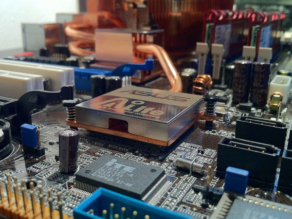
In Figure 1, you can see the ASUS P8P67 PRO motherboard.

ASUS P8P67 PRO motherboardFigure 1: ASUS P8P67 PRO motherboard

[nextpage title=”Slots”]

The ASUS P8P67 PRO comes with three PCI Express x16 slots, two PCI Express x1 slots, and two standard PCI slots.

The first two PCI Express x16 slots are connected directly to the CPU integrated PCI Express controller. When only one video card is installed, the first slot (blue) works at x16 speed, but when you install two video cards, the first two slots work at x8 speed. These slots support both SLI and CrossFireX technologies.

The third PCI Express x16 slot (black) works at x1 or x4 speeds. Since the P67 chipset doesn’t provide enough PCI Express lanes, by default the third PCI Express x16 slot works at only x1 speed. If you want to make it work at x4 speed, you will have to manually disable the eSATA ports, the internal USB 3.0 header (USB3_34) and the PCI Express x1 slots on the motherboard setup. If this motherboard had a PCI Express switch chip, it would be able to automatically switch the speed of the third PCI Express slot.

It is always good to remember that PCI Express x16 slots accept x1, x4, x8, and x16 expansion cards directly.

If you install a dual-slot video card in the first PCI Express x16 slot, you will “kill” one of the PCI Express x1 slots. If you install a dual-slot video card in the second PCI Express x16 slot, you will “kill” one of the standard PCI slots. And to install a dual-slot video card in the third PCI Express x16 slot, you will need a case with at least eight expansion slots (computer cases usually have seven), and you may block the USB and FireWire headers located at the motherboard edge.

It is important to understand that Intel chipsets no longer support standard PCI slots, and the PCI slots are provided by an ASMedia ASM1085 bridge chip.

ASUS P8P67 PRO motherboardFigure 2: Slots

[nextpage title=”Memory Support”]

Intel socket LGA1155 CPUs have an embedded memory controller, meaning that it is the processor, not the chipset, that defines what memory technologies as well as the maximum amount of memory you can have. The motherboard, however, may have a limitation as to how much memory can be installed.

The integrated memory controller from socket LGA1155 processors supports DDR3 memories up to 1,333 MHz under dual-channel architecture, but ASUS says the P8P67 PRO supports memory up to 2,133 MHz through overclocking.

The ASUS P8P67 PRO has four memory sockets, and since DDR3 memory modules can now be found in capacities up to 8 GB, you can have up to 32 GB with this motherboard if you use four 8 GB modules.

The first and third sockets are light blue, while the second and fourth are black. In order to achieve the maximum performance, you should install two or four memory modules in order to enable dual-channel architecture. When only two modules are used, install them in the light blue sockets. Otherwise, your computer won’t turn on.

ASUS P8P67 PRO motherboardFigure 3: Memory sockets; install two or four modules for the best performance

As with other motherboards from ASUS, the P8P67 PRO comes with the “MemOK!” button, which allows you to test the compatibility of the memory modules that are installed.

ASUS P8P67 PRO motherboardFigure 4: The “MemOK!” button

[nextpage title=”On-Board Peripherals”]

The Intel P67 chipset is a single-chip solution and is also known as PCH (Platform Controller Hub). This chip supports two SATA-600 ports and four SATA-300 ports, supporting RAID (0, 1, 5 and 10). The manufacturer added two additional SATA-600 ports, controlled by a Marvell 88SE9172 chip (RAID 0 and 1). The SATA ports are located on the motherboard edge rotated 90°, so video cards won’t block them.

ASUS P8P67 PRO motherboardFigure 5: SATA-300 ports (light blue), SATA-600 ports controlled by the c
hipset (gray), and SATA-600 ports controlled by the Marvell chip (dark blue)

Additionally, there are two eSATA-300 ports on the motherboard rear panel, controlled by a JMicron JMB362 chip. One of them (the red one) is a regular eSATA port, but the other (the green one) is a “power eSATA” port, which has extra pins for power.

There is no support for a floppy disk drive controller or an ATA-133 port.

This motherboard has 12 USB 2.0 ports, six soldered on the rear panel and six available through three headers located on the motherboard. It also has four USB 3.0 ports, two available on the motherboard rear panel and two available through a front panel connector, controlled by two NEC (Renesas) µPD720200 chips. The motherboard comes with an I/O bracket for you to use the internal USB 3.0 header, if your computer case doesn’t have two USB 3.0 ports with an internal connector.

This motherboard has two FireWire ports, one soldered on the rear panel and one available through a header on the motherboard. These ports are controlled by a VIA VT6308P chip.

This motherboard supports 7.1+2 audio format, i.e., eight channels plus two independent channels for audio streaming. On this motherboard, the audio is generated by the chipset using a Realtek ALC892 codec. Finally, Realtek is disclosing the specifications of this chip, which include a 97 dB signal-to-noise ratio for the analog outputs, a 90 dB signal-to-noise ratio for the analog inputs, and up to 192 kHz sampling rate for both inputs and outputs. These specs are good for the mainstream user, but if you are looking into working professionally with audio editing, you should look for a motherboard that provides an SNR of at least 97 dB for the analog input.

The portrayed motherboard comes with independent analog audio outputs, meaning that you won’t need to use the line in or mic in jacks when connecting an eight-channel analog speaker set, and an optical and coaxial SPDIF output. You also can route digital audio to your video card to have digital audio in its HDMI connector using the available “SPDIF_OUT” header.

This motherboard has one Gigabit Ethernet port, controlled by the chipset, using an Intel WG82579V chip to make the interface with the physical layer.

The P8P67 PRO has a Bluetooth receiver.

In Figure 6, you can see the motherboard rear panel, with PS/2 mouse and keyboard connectors, coaxial and optical SPDIF outputs, Bluetooth receiver, six USB 2.0 ports, two eSATA-300 ports, one FireWire port, one Gigabit Ethernet port, two USB 3.0 ports (blue ones), and independent analog 7.1 audio outputs.

ASUS P8P67 PRO motherboardFigure 6: Motherboard rear panel

[nextpage title=”Other Features”]

The motherboard has on-board power and reset buttons, and two switches, labeled TPU and EPU. The EPU switch enables or disables the power-savings features available, while the TPU switch enables or disables automatic overclocking. The TPU switch is located near the third PCI Express slot, while the EPU switch is located near the “MemOK!” button. In Figure 7 you see the TPU switch, while the EPU switch was already shown in Figure 4.

ASUS P8P67 PRO motherboardFigure 7: TPU switch

If your computer doesn’t turn on, the product has four LEDs that tell you which device (CPU, memory, first video card or boot device) failed to initialize. Unfortunately, these LEDs are spread on the motherboard instead of being placed together at the same location.

In Figure 8, you can see all the accessories that come with this motherboard.

ASUS P8P67 PRO motherboardFigure 8: Accessories

[nextpage title=”Voltage Regulator”]

The CPU voltage regulator circuit of the ASUS P8P67 PRO has 12 phases for the CPU main voltage (Vcc a.k.a. Vcore) and two for the CPU VTT voltage (integrated memory controller and L3 memory cache). Therefore, it uses a “12+2” configuration, using a digital design.

ASUS P8P67 PRO motherboardFigure 9: Voltage regulator circuit

ASUS P8P67 PRO motherboardFigure 10: Voltage regulator circuit

This motherboard uses military-grade components, including solid ferrite-core coils, which present less energy loss than iron-core coils (i.e., they improve efficiency), solid capacitors, and low RDS(on) transistors (i.e., higher efficiency).

If you want to learn more about the voltage regulator circuit, please read our tutorial on the subject.  [nextpage title=”Overclocking Options”]

The ASUS P8P67 PRO offers some overclocking options, listed below (1850 BIOS):

  • CPU base clock: From 80 MHz to 300 MHz in increments of 0.1 MHz
  • CPU core voltage: From -0.640 V to +0.640 V in increments of 0.005 V
  • CPU VTT (VCCIO) voltage: From 0.80000 V to 1.70000 V in increments of 0.00625 V
  • CPU system agent (VCCSA) voltage: From 0.80000 V to 1.70000 V in increments of 0.00625 V
  • CPU PLL voltage: From 1.20000 V to 2.20000 V in increments of 0.00625 V
  • Chipset (PCH) voltage: From 0.80 V to 1.70 V in increments of 0.01 V
  • Memory voltage: From 1.20000 V to 2.20000 V in increments of 0.00625 V
  • Voltage regulator (VRM) clock: From 300 kHz to 500 kHz in increments of 10 kHz

For a better understanding of what these options do, please read our Understanding All Voltage Configurations from the Motherboard tutorial.

ASUS P8P67 PRO motherboardFigure 11: Overclocking options

ASUS P8P67 PRO motherboardFigure 12: Overclocking options

ASUS P8P67 PRO motherboardFigure 13: Overclocking options

ASUS P8P67 PRO motherboardFigure 14: Memory timings options

[nextpage title=”Main Specifications”]

The main specifications for the ASUS P8P67 PRO motherboard include:

  • Socket: 1155
  • Chipset: Intel P67 Express
  • Super I/O: Nuvoton NCT6776F
  • Parallel ATA: None
  • Serial ATA: Four SATA-300 and two SATA-600 ports controlled by the chipset (RAID 0, 1, 5, and 10), and two SATA-600 ports controlled by a Marvell 88SE9172 chip (RAID 0 and 1)
  • External SATA: Two eSATA-300 ports controlled by a JMicron JMB362 chip
  • USB 2.0: 12 USB 2.0 ports, six soldered on the motherboard rear panel and six available through three headers on the motherboard
  • USB 3.0: Four ports, two soldered on the motherboard rear panel and two available through one header on the motherboard, controlled by two NEC (Renesas) µPD720200 chips
  • FireWire (IEEE 1394): Two ports, one available on the rear panel and available through a header on the motherboard, controlled by a VIA VT6308P chip
  • On-board video: No
  • On-board audio: Produced by the chipset together with a Realtek ALC892 codec (eight channels, 24-bit resolution, up to 192 KHz sampling rate for both the inputs and outputs, 90 dB signal-to-noise ratio for the inputs and 97 dB signal-to-noise ratio for the outputs), on-board coaxial and optical SPDIF connectors
  • On-board LAN: One Gigabit Ethernet port controlled by the chipset and using an Intel WG82579V chip for the physical layer interface
  • Buzzer: No
  • Infrared interface: No
  • Power supply required: EPS12V
  • Slots: Three PCI Express 2.0 x16 slots (first two at x16/x0 or x8/x8, supporting SLI and CrossFireX, third at x1 or x4), two PCI Express x1 slots, and two standard PCI slots (ASMedia ASM1085 bridge chip)
  • Memory: Four DDR3-DIMM sockets (up to DDR3-2133, 32 GB maximum)
  • Fan connectors: One four-pin connector for the CPU cooler, one four-pin connector for an auxiliary fan, and two three-pin connectors for auxiliary fans
  • Extra Features: Bluetooth receiver, POST diagnostics LEDs, “MemOk!” button, TPU and EPU switches
  • Number of CDs/DVDs provided: One
  • Programs included: Motherboard utilities
  • More Information: https://usa.asus.com
  • Average price in the US*: USD 180.00

* Researched at Newegg.com on the day we published this First Look article.

[nextpage title=”Conclusions”]

The ASUS P8P67 PRO is targeted to the user who is building a computer based on an Intel CPU and wants more features than “normal” socket LGA1155 motherboards can provide, such as a Bluetooth receiver, on-board optical and coaxial SPDIF outputs, two additional SATA-600 ports for a total of four, four USB 3.0 ports, two eSATA-300 ports, two FireWire ports, a third PCI Express x16 slot, more overclocking options, and a better-than-average voltage regulator circuit.

It is important to keep in mind that this third PCI Express x16 slot works, by default, at x1 speed. If you want it to work at x4, you will have to manually disable the eSATA ports, the internal USB 3.0 ports (USB3_34) and the PCI Express x1 slots on the motherboard setup. High-end motherboards based on the P67 chipset usually have a PCI Express switch chip to automatically switch the speed of the third PCI Express slot depending on the devices you are currently using.

Reader Interactions

Leave a Reply Cancel reply

Your email address will not be published. Required fields are marked *

Primary Sidebar

As a participant in the Amazon Services LLC Associates Program, this site may earn from qualifying purchases. We may also earn commissions on purchases from other retail websites.

car service

Why Is Fleet Maintenance Important?

If you have a fleet of vehicles you use within your business, it’s crucial you keep up with their

Playing Fifa on Play station 4

Tips for Recycling Your Gaming Consoles and Devices

These days, it seems like almost everybody is gaming. As great as this is, it’s also creating a

Business planning

How to Develop Your Venture Capital Business

Venture Capital (VC) is a type of private equity investment in which investors provide funding to

Footer

For Performance

  • PCI Express 3.0 vs. 2.0: Is There a Gaming Performance Gain?
  • Does dual-channel memory make difference on integrated video performance?
  • Overclocking Pros and Cons
  • All Core i7 Models
  • Understanding RAM Timings

Everything you need to know

  • Everything You Need to Know About the Dual-, Triple-, and Quad-Channel Memory Architectures
  • What You Should Know About the SPDIF Connection (2022 Guide)
  • Everything You Need to Know About the Intel Virtualization Technology
  • Everything You Need to Know About the CPU Power Management

Copyright © 2023 · All rights reserved - Hardwaresecrets.com
About Us · Privacy Policy · Contact