In this tutorial we will explain everything you need to know about PC power supplies, including form factors, efficiency, power factor correction (PFC), rails, protections, ripple and much more. You will learn that the power supply power rating should not be the only factor to consider when buying a power supply unit.
But before going further, let’s explain exactly what a power supply does.
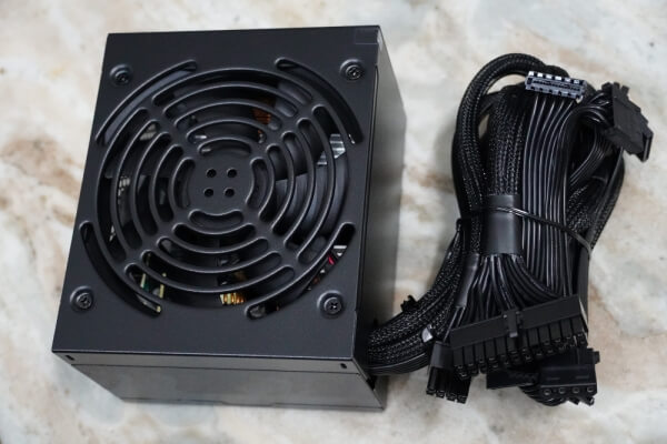
As an electrical device, the computer needs power in order for its components to operate properly. The device responsible for supplying power to the computer is the power supply. In short, we could say that the main function of the power supply is to convert alternating voltage (a.k.a. AC), which is supplied by the electrical power system into continuous voltage (a.k.a. DC). In other words, the power supply converts the conventional 110V or 220V alternating voltage into continuous voltage used by the PC electronic components, which are +3.3 V, +5 V, +12 V and -12 V (Alternating voltages vary throughout the world. In this tutorial, we will use “110 V” as a catchall label for 110 V, 115 V and 127 V voltages, whereas we will use “220 V” as a catchall label for 220 V, 230 V and 240 V voltages. Japan, which uses a 100V power grid, is the only country outside this range.) The power supply is also present in the PC cooling process, as we will explain in detail later.
There are two basic power supply designs: linear and switching-mode.
Linear power supplies work by getting the 110 V or 220 V from the power grid and lowering its value (e.g., 12 V) by using a transformer. This lower voltage is still AC. Then rectification is done by a set of diodes, transforming this AC voltage into pulsating voltage. The next step is filtering, which is performed by an electrolytic capacitor, transforming this pulsating voltage into almost DC. The DC obtained after the capacitor oscillates a little (this oscillation is called ripple), so a voltage regulating stage is necessary, made by a zener diode (frequently with the aid of a power transistor) or by a voltage regulator integrated circuit. After this stage the output is true DC voltage.
Although linear power supplies work very well for several low-power applications – cordless phones is an application that comes to mind – when high power is needed, linear power supplies can be very large.
The size of the transformer and the capacitance (and thus the size) of the electrolytic capacitor are inversely proportional to the frequency of the input AC voltage; the lower the AC voltage frequency, the bigger the size of those components and vice-versa. Since linear power supplies still use the 60 Hz (or 50 Hz, depending on the country) frequency from the power grid (which is a very low frequency), the transformer and the capacitor are huge.
Building a linear power supply for the PC would be insane, since it would be very big and heavy. The solution was to use the high-frequency switching approach.
On high-frequency switching mode power supplies (a.k.a. SMPS), the input voltage has its frequency increased before going into the transformer (in the range of kHz are typical values). With input voltage frequency increased, the transformer and the electrolytic capacitors can be very small. This is the kind of power supply used on the PC and several other types of electronic equipment, such as DVD players. Keep in mind that “switching” is short for “high-frequency switching,” which has nothing to do with whether the power supply has an on/off switch or not…
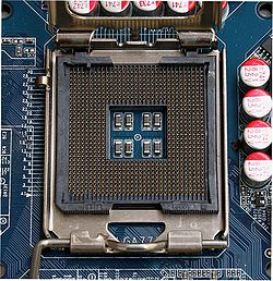
The power supply is probably the most neglected component on PC. Usually when buying a computer, we just take on account the processor type and clock, the motherboard model, the video card model, the quantity of installed memory, the hard disk storage capacity, and we forget about the power supply, which, in fact, is the one who supplies the “fuel” for the PC parts to operate properly.
A power supply of good quality and with enough capacity can increase the durability of your equipment and reduce your electricity bill (we will explain why when discussing efficiency). Just to get an idea, a high-quality power supply will cost less than 5% of the PC total price. On the other hand, a low-quality power supply can cause several intermittent problems, most of which are difficult to solve. A defective or bad-intentioned power supply can lock the PC, result in hard disk bad blocks, cause the infamous “blue screen of death” errors, andgive rise to random resets and freezings, added to many other problems.
In this tutorial, we will discuss the basics that every user should know. If you want to learn even more about the internals of a PC power supply we recommend that after reading this tutorial, you read its sequel, Anatomy of Switching Power Supplies, where we explain in detail how the major internal components of a PC power supply work.
[nextpage title=”AC Connection”]
The first thing you should know is that your power supply must be compatible with the AC voltage used in your city. The most common ones are “110 V,” covering voltages that approximate this value (for example, 115 V and 127 V), and “220 V”(for example, 230 V and 240 V).
Most power supplies will have either a 110 V/220 V switch or will be “auto range” or “auto select,” meaning that they can work under “any” AC voltage (usually between 100 V and 240 V; the range is printed on the power supply label, under “AC Input,” see Figure 3) Therefore, they don’t come with this kind of switch. Usually manufacturers make the “auto select” circuit through the active PFC circuitry, so all power supplies with active PFC will be “auto range” and won’t have a 110 V/220 V switch. Only a very few power supplies with automatic voltage selection won’t have an active PFC feature. Of course we will explain what this circuit is later.
Not all power supplies that don’t have a 110 V/220 V switch are auto range. Some power supplies can only operate under a specific voltage. These are most commonly targeted to the European market. If you see a power supply without a 110 V/ 220 V, it is always a good idea to double check the power supply label under which the AC voltage can work.

Figure 1: Power supply 110 V/220 V switch.

Figure 2: Power supply with auto voltage select – no 110 V / 220 V switch. Usually this means that the unit has active PFC.

Figure 3: The voltage range for power supplies with auto voltage select is described on the power supply label.
The connection between your power supply and the AC outlet is done through a power cord. This power cord must use a plug compatible with the standard used in your country. If your plug doesn’t conform to that standard, you will need to use an adapter. The two most common plug types are the North-American (NEMA 5-15) and the European (CEE 7/7). Other countries may use different plug types (for example, the UK use a plug called BS 1363).

Figure 4: North-American power cord.

Figure 5: European power cord.
The end of the power cord that is connected to the power supply uses a trapezoid-shaped plug called an IEC C13, while the receptacle for the power cord located on the power supply uses a plug called an IEC C14. Other plugs can also be used on this connection, such as an IEC C19 and an IEC C20, but they are not as common.
[nextpage title=”Power Plugs”]
Nowadays, power supplies provide the following connectors to feed the components from the PC:
- Main motherboard connector: This is one of the cables that you need to connect to the PC motherboard. It uses a big 24-pin plug, which is the biggest plug found on the power supply. Most power supplies will allow you to convert this 24-pin plug into a 20-pin plug (usually by removing the extra 4 pins), which is the standard used by older motherboards. Motherboards that use the 24-pin connector are called ATX12V 2.x, while motherboards that use the 20-pin connector can be either an ATX12V 1.x motherboard or an ATX motherboard. Note that these names refer to the electrical connection of the motherboard and not to the motherboard’s physical size. ATX is also a name used to describe the size of the motherboard, which can be confusing for some users (you can have an ATX motherboard with an ATX12V 2.x connector). For example, in this case ATX refers to the size of the motherboard, 12” x 9.6” or 30.5 cm x 24.4 cm.
Figure 6: Main motherboard connector (24-pin plug). See how it can be transformed into a 20-pin connector.
Figure 7: Main motherboard connector (24-pin plug).
- ATX12V connector: This 4-pin connector is used to provide electrical current to the system CPU and must be installed on the motherboard. The installation of this connector is required – unless you use the EPS12V connector (see below).
Figure 8: ATX12V connector.
Figure 9: ATX12V connector.
- EPS12V connector: This 8-pin connector has the same function as ATX12V, i.e., to provide electrical current to the system CPU. Since it has eight pins instead of four, it is capable of providing more current. Not all power supplies and not all motherboards come with this connector. On some power supplies, the EPS12V connector is obtained by putting together two ATX12V connectors. If your motherboard and your power supply both have this connector, use it instead of using the ATX12V one. Motherboards that come with this connector often come with half of the connector covered with a sticker or a plastic cover, allowing you to use the power supply ATX12V connector on the motherboard EPS12V connector. You can install the ATX12V connector from the power supply on the EPS12V connector on the motherboard, however this isn’t recommended.
Figure 10: EPS12V connector.
Figure 11: On some power supplies, the EPS12V connector is obtained by putting together two ATX12V connectors.
Figure 12: EPS12V connector on a motherboard.
[nextpage title=”Power Plugs (Cont’d)”]
- PCI Express auxiliary power connectors: These connectors are used to provide more electrical current to PCI Express devices, especially video cards. Therefore, they are also called video card power connectors or simply PEG (PCI Express Graphics). Not all video cards require extra power, but if your video card has this kind of plug you must install the power supply auxiliary power connector. These connectors can have six or eight pins. Almost all video cards that need extra power require the 6-pin version of this connector; only very high-end video cards require the 8-pin type. Some very high-end video cards can even require the use of two auxiliary power cables to feed them. You must pay close attention to the 8-pin connector, because it looks a lot like the EPS12V connector. Though in theory, you can’t insert an EPS12V plug on a video card, if you push really hard, this connection becomes possible. However, it can also lead to a massive short-circuit. Fortunately, all power supplies have a short-circuit protection and won’t turn on if you make this mistake. On the EPS12V connector, the +12 V (yellow) wires are located on the same side of the small latch present on the connector, while on the 8-pin video card power plug, the ground (black) wires are the ones located in that position. Currently, all power supplies must have at least one 6-pin plug, with higher-wattage models providing two, three or four cables, providing extra power to more than one video card or additional power for the very high-end video cards that require two power cables. You can also transform any standard peripheral power plug into a video card power connector through an adapter. This is quite handy if you are installing an additional video card or have an old power supply and don’t want to replace your unit.
Figure 13: The six-pin PEG connector. This particular power supply provides two extra pins for you to transform this 6-pin plug into an 8-pin one. We call this kind of connector a 6/8-pin connector.
Figure 14: A six-pin PEG connector on a video card.
- SATA power connectors: This kind of plug is used to provide power to serial ATA (SATA) devices such as hard disk drives and optical disk drives. If your power supply doesn’t have enough of these plugs for your system, you can convert any standard peripheral power plug into a SATA power plug through the use of an adapter. Physically, it is flat and has 15 pins.
Figure 15: SATA power plug.
Figure 16: SATA power connector on a hard disk drive.
- Peripheral connectors: This is a 4-pin trapezoid-shaped general-purpose power connector that is frequently used to feed hard disk drives, optical drives, fans, lightning systems, etc. Though currently, new hard disk drives and optical drives are connected to the power supply through SATA power connectors. Before the release of the PEG connector, high-end video cards used this kind of plug for providing extra power to the card. These connectors have existed since the very first IBM PC from 1981, and IBM used a company called Molex as their vendor for them. Many people called these plugs “Molex,” only because on the first PCs, you could read “Molex” on them. People thought this was the name of the connector, not realizing that Molex was the manufacturer. We prefer to call them “standard peripheral power plugs.”
Figure 17: Standard peripheral power plug.
Figure 18: Standard peripheral power connector on an optical unit.
- Floppy disk drive power connector: This is the smaller version of the previous plug, used to provide power to 3.5” floppy disk drives. A few older video cards used this plug to provide extra power to them instead of using the previous connector.
Figure 19: Floppy disk drive power connector.
Figure 20: Power connector on a floppy disk drive.
[nextpage title=”Older Power Plugs”]
The two plugs described below aren’t used anymore, but you may find them while disassembling old PCs.
- Motherboard six-pin auxiliary power connector: This connector was released together with ATX12V 1.x specification, but only a few motherboards (most notably socket 423 and early socket 478 boards) used it.
Figure 21: Six-pin auxiliary power connector.
- Motherboard 12-pin connector: This connector was the main motherboard connector on AT motherboards and
AT power supplies. It became obsolete with the introduction of the ATX standard. It used two six-pin connectors and the problem was that these two six-pin connectors could be inserted on any side of the 12-pin connector found on the motherboard. In order to avoid mistakes you must install these connectors in a way that the black wires are placed on the center of the connector (see Figure 22).
Figure 22: AT power connector.
[nextpage title=”Form Factors”]
There are several different form factors (or “standards”) for PC power supplies. These form factors define not only the physical size of the power supply, but also the kind of connectors the power supply has. As of this writing ATX12V 2.x and EPS12V are the most common standards for PC power supplies.
- AT: This standard was introduced by the IBM PC AT in 1984 and was used until the ATX standard gained popularity in the mid-1990’s. This power supply delivers four voltages, +5 V, +12 V, -5 V and -12 V, and the main motherboard connector uses a 12-pin connector (see previous page). From the connectors presented this kind of power supply uses only the standard peripheral power connectors and the floppy disk drive power connector, in addition to the 12-pin motherboard cable.
- ATX: In 1996, Intel introduced a new motherboard layout called ATX to replace the old AT layout. Because the ATX motherboard had completely different physical dimensions, new cases were also needed (“ATX cases,” in contrast to the “AT cases” used so far). With this new motherboard layout, Intel also proposed a new kind of power supply providing new features, such as the use of a new 20-pin motherboard connector and the introduction of two new voltages, +3.3 V and +5VSB, also known as “standby power.” This output is always turned on, even when the computer is turned off, which allows the computer to turn itself off without requiring you to press an on/off switch. From the connectors presented, this kind of power supply uses only a 20-pin motherboard connector, the standard peripheral power connectors and the floppy disk drive power connector. You can find the complete ATX specification here.
- ATX12V 1.x: With modern CPUs requiring more power, two extra connectors were added to ATX power supplies: a four-pin 12 V connector (ATX12V connector) and a six-pin auxiliary power (see previous page). ATX12V 1.3 introduced the Serial ATA power connector. You can find the complete ATX12V 1.x specification here.
- ATX12V 2.x: This form factor, introduced with the release of the PCI Express bus, upgraded the main motherboard power connector to a 24-pin model (Figures 6 and 7) and introduced the PCI Express auxiliary power connector (PEG, Figures 13 and 14). You can find the complete ATX12V 2.x specification here. This is the standard used nowadays.
- EPS12V: This form factor was created by SSI (Server System Infrastructure) for entry-level servers. Its current version uses the same plugs used on the ATX12V 2.x, adding a new CPU power plug, called EPS12V (see Figures 10, 11 and 12). Since it brings only one new connector, many power supply manufacturers provide models that are ATX12V v2.x and EPS12V at the same time. You can find the complete EPS12V specification here.
So far we took a look at the main power supply form factors for desktop PCs. There are, however, other form factors available for small form factor PCs.
- LFX12V: LFX stands for Low Profile Form Factor. It uses the same connectors as ATX12V v2.x but has a different physical size: 2.44” x 2.83” x 8.27” (62 mm x 72 mm x 210 mm) (W x H x D).
Figure 23: LFX12V power supply.
- CFX12V: CFX stands for Compact Form Factor. It uses the same connectors as ATX12V v2.x and is “L” shaped based on the standard ATX size, with a 5.90” (150 mm) width at its top and 4” (101.6 mm) width at its bottom. You can find the complete CFX12V specification here.
- TFX12V: TFX stands for Thin Form Factor. It uses the same connectors as ATX12V v2.x but has a different physical size: 2.56” x 3.35” x 6.89” (65 mm x 85 mm x 175 mm) (W x H x D). You can find the complete TFX12V specification here.
- SFX12V: SFX stands for Small Form Factor. You can find the complete SFX12V specification here. It uses the same connectors as ATX12V v2.x and can be found in several different physical sizes and fan configurations:
- 3.94” x 1.97” x 4.92” (100 mm x 50 mm x 125 mm) (W x H x D) (a.k.a. 40mm Fan Profile)
- 3.94” x 2.5” x 4.92” (100 mm x 63.5 mm x 125 mm) (W x H x D) (a.k.a. Top Mount Fan Profile)
- 4.92” x 2.5” x 3.94” (125 mm x 63.5 mm x 100 mm) (W x H x D) (a.k.a. Reduced Depth Top Mount Fan Profile)
- 3.94” x 2.5” x 4.92” (100 mm x 63.5 mm x 125 mm) (W x H x D) (a.k.a. 60mm Fan Profile)
- 5.43” x 3.38” x 3.99” (138 mm x 86 mm x 101.4 mm) (W x H x D) (a.k.a. PS3 Profile)
[nextpage title=”Cooling”]
The power supply plays a crucial role in the process of cooling the PC. Its exact function is to remove hot air out of the case. The air flow inside the PC works as follows. The cold air enters through the grooves found in the frontal part of the case. The air is heated by devices such as the processor, video card, chipset, etc. As hot air is less dense than cold air, the natural tendency is to rise. Consequently, hot air is retained in the top of the case. The power supply cooling fan works as an exhaust fan, pulling hot air from this area and blowing it out of the PC. See how this works in Figure 24. Hi-end power supplies have two or three cooling fans. Some cases have appropriate space for installing an extra fan at the rear.
Figure 24: Airflow inside the PC case.
Traditionally, PC power supplies use an 80 mm fan on their rear side, as you can see in Figure 25. Some years ago, power supply manufacturers started using a 120 mm or bigger fan on the bottom of the power supply, replacing the rear panel of the power supply with a mesh. Usually, the use of a bigger fan provides a higher airflow and a lower noise level, because a bigger fan can rotate at a lower speed in order to produce the same airflow as a smaller fan.
Figure 25: Power supply with an 80 mm on the rear.
Figure 26: Power supply with a 120 mm on the bottom.
Some power supplies may have more than one fan, while a few manufacturers provide speed control to the power supply fan or a cable for you to monitor the fan speed through your favorite monitoring program. This cable must be installed on an empty fan header on the motherboard. (These features are not so common.)
The problem with a power supply fan and/or extra fans is the noise produced by them. Sometimes, it’s such an irritating noise that simply working with the computer causes us stress. In order to reduce noise, currently, most power supplies use a circuit to control the fan speed according to the power supply internal temperature. When the power supply is cold the fan spins at a lower speed, thus producing less noise.
In order to provide a better airflow and organization inside the PC, some power supplies use a modular cabling system, where instead of being permanently attached to the power supply, peripheral cables are attached to the unit using connectors. You can remove the cables you won’t use. Some manufacturers also sell extra cables for their power supplies’ modular cabling system, helping users for future upgrades. Usually on power supplies using modular cabling systems the main motherboard cable and the ATX12V/EPS12V cables are permanently attached to the unit, as shown in the power supply portrayed in Figure 27.
Figure 27: Modular cabling system.
[nextpage title=”Power”]
Power supplies are labeled according to the maximum power they can deliver – at least in theory. The problem is that a lot of power supplies can’t deliver their labeled power, typically because the manufacturer:
- Labeled the power supply with peak wattage, which can only be achieved for a few seconds and, in some cases, in less than one second.
- Measured the power supply maximum wattage with an unrealistic room temperature, normally 25° C (77° F), while the temperature inside the PC will always be higher than that – at least 35° C (95° F). Semiconductors and inductors have a physical effect called de-rating where they lose their ability to deliver current (and thus power) with an increase in temperature (see Figure 28). So a maximum power measured at a lower temperature may not be achieved when temperature is increased.
- Simply lied. This is probably the case with “generic” units.
To illustrate the effect that temperature makes on the ability of a power supply to deliver current, consider the de-rating curve presented in Figure 28, which belongs to a transistor called FQA24N50. As you can see, this transistor can deliver up to 24 A when working at 25° C (77° F), but as soon as temperature increases (x axis), the maximum supported current (y axis) decreases. At 100° C (212° F), the maximum current this device can deliver is 15 A, a 37.5% decrease. Power, which is measured in watts, is a factor between current and voltage (P = V x I). If this transistor were operating at 12 V, we would see a decrease in the maximum power from 288 W (12 V x 24 A) to 180 W (12 V x 15 A).
Figure 28: De-rating curve of a transistor.
Knowing this situation, reputable manufacturers started to disclose at what temperature their power supplies were labeled. You can find some power supplies on the market where the manufacturer guarantees that they can deliver their labeled power at 40° C, 45° C or even at 50° C. In other words, the manufacturer guarantees that they can deliver their labeled power in a real-world scenario not only at the manufacturer’s lab. This is a reliable parameter when deciding which power supply to buy.
You may think that the maximum amount of power a power supply can deliver is simply the sum of the maximum amount of power each output can deliver. In truth, the math isn’t that simple because of the way PC power supplies work internally. The main positive outputs (+12 V, +5 V and +3.3 V) share some components, so even though each output has an individual maximum output, this maximum can only be reached when no power is being pulled from the other outputs.
The most common case is the +5 V and +3.3 V outputs. Even though they have individual maximum current and power limits, these maximum values can only be pulled when no power is being pulled from the other output. Together they have a combined maximum power, which is lower than the simple addition of the maximum capacity from +5 V and +3.3 V outputs.
For a practical example, consider the power supply in Figure 29. Its label says that the +5 V output can deliver up to 24 A, which equates to 120 W, or 5 V x 24 A. The +3.3 V output can also deliver up to 24 A, which equates to 79.2 W, or 3.3 V x 24 A. The maximum combined power printed on the label is 155 W, (less than the simple addition of the maximum power each output can deliver individually), which would be 199.2 W, or 120 W + 79.2 W.
The same idea holds true for the +12 V outputs. On the power supply from Figure 29, each +12 V rail can deliver up to 16 A (192 W, or 12 V x 16 A), but the maximum combined power for the +12 V outputs is 504 W, not 768 W (192 W x 4).
And finally, we have a combined power for the +12 V, +5 V and +3.3 V at the same time, which isn’t a simply addition of the maximum combined power for the +5 V/+3.3 V outputs with the maximum combined power for the +12 V outputs. On the power supply from our example, the maximum combined power for these outputs is 581.5 W and not 659 W (155 W + 504 W).
Figure 29: A typical power supply label.
Finally, we have power distribution, something about which very few users are aware. Two power supplies with the same maximum power can have a completely different power distribution.
Nowadays, a typical PC pulls more power from the +12 V outputs. This occurs because the two most power-hungry components from the PC – the CPU and the video card – are connected to the + 12 V outputs (through the ATX12V/EPS12V connector and through the PEG connector, respectively).
Take another look at the power supply label from Figure 29. From this label, you can clearly see that this power supply uses an updated project, where the power supply is capable of delivering more power from the +12 V outputs (504 W) than from the +3.3 V/+5 V outputs (155 W).
Now consider the power supply from Figure 30. This unit can deliver more power/current from its +5 V/+3.3 V outputs than from its +12 V outputs, meaning that
this power supply uses an outdated design. Believe it or not, this power supply is still being sold, and there are several power supplies with outdated designs around.
Figure 30: Label of a power supply with an outdated design.
In summary, buy power supplies where the maximum capacity is on the +12 V outputs and not on the +5 V/+ 3.3 V lines.
Finally, you will need to know how much power your PC will really consume before picking a power supply. There are several calculators on the Internet that can help you out with this; we recommend this one. We also recommend that you choose a power supply that will be working between 40% and 60% of its maximum capacity. There are two reasons for this. The first is efficiency, a subject that we will explain next. Second, you will have headroom for future upgrades. Get the result obtained from the calculator and multiply it by 2. This is the power supply wattage we recommend that you buy. (You will be surprised that most systems will require a power supply with less than 450 W, even with our adjustment.)
[nextpage title=”Efficiency”]
The efficiency of a power supply shows how much of the power being pulled from the power grid is being effectively converted into DC. Efficiency is the ratio between the power being pulled from the wall and the power actually being delivered to the PC.
Efficiency = DC power / AC power
For example, if your PC is consuming 250 W and your power supply is pulling 350 W from the wall, this means that your power supply efficiency is 71.4 percent.
Good power supplies will provide an efficiency of at least 80%, the higher, the better. We recommend that you buy power supplies with at least 80% efficiency.
A power supply with higher efficiency brings two advantages. First, it results in a lower electricity bill. Using the same example as above, if you replaced that power supply with a unit with 80% efficiency, you would be pulling only 312.5 W from the wall, thereby saving 37.5 W. If you use your computer a lot (for instance, during the whole day, every day), this savings is noticeable, and in the end, it pays off to buy a power supply with higher efficiency, even if it initially costs a little more.
The second advantage is that less heat is being produced. In our first example, the power supply would be converting 100 W into heat, while in our second example, the heat dissipation would drop to 62.5 W, a 37.5% decrease in heat dissipation. This is really nice, and it is always good to keep our computers running as coolly as we can.
If you see a typical efficiency curve, you will notice that efficiency varies according to the power being delivered. Usually, the power supply achieves its highest efficiency when delivering between 40% and 60% of its maximum capacity. Efficiency is also higher when the power supply is operating at 220 V. See Figure 31 for a real example.
Figure 31: Example of an efficiency curve.
Because of this effect, it is recommended that you buy a power supply with double the power you are actually going to pull. This explains the offer of high-wattage power supplies above 700 W. Manufacturers don’t expect you to pull the full power from their units, but that you operate them around 50% load for a higher efficiency. During our reviews, however, we need to see if the power supply can really deliver its labeled power, because if a power supply is labeled as, let’s say, a 600 W unit, we want to be capable of pulling 600 W from it, if we so desire). The only disadvantage to this approach is the price of a higher wattage unit. But in the long run, it is a good idea, as you will save money on your electricity bill, your computer will run cooler, you will have enough headroom for a future upgrade, and you won’t face any stability problems when playing games at their maximum quality for hours. As we mentioned, you will be surprised that most systems will require a power supply with less than 450 W, even with our adjustment.
Read our Understanding the 80 Plus Certification to learn more about the 80 Plus efficiency certification.
[nextpage title=”Power Factor Correction (PFC)”]
All equipment with motors and transformers, such as the power supply itself, use two types of power: active (measured in kWh) and reactive (measured in kVArh). Active power produces the real work, for example, a motor axe rotation. Reactive power (also called magnetizing power) is the power required to produce the magnetic fields to enable the real work to be done on transformers, motors, etc. The vector sum of the reactive power and the real power components is called apparent power and is measured in kVAh. For the industrial customer, the electrical power utilities measure and charge based on the apparent power, but for residential and commercial customers, the measured and charged power is the active power.
The problem is that, although it’s necessary for motors and transformers, the reactive power “occupies space” on the system which could be used by more active power.
Power factor is the ratio between the active power and the apparent power of a circuit (power factor = active power / apparent power). This ratio can vary from 0 (0%) to 1 (100%), and the nearest to 1 this factor is, the better, because it means that the circuit is absorbing less reactive energy.
In order to optimize reactive power consumption, many countries have established through legislation the maximum reactive power percentage to be consumed by users. If the customer has a power factor inferior to the value set up by the government (i.e., the reactive power is above the limit set up by law), the customer will pay a penalty.
The penalty concept exists to force industry to improve its power factors in order to prevent them from using more reactive power. As we have already mentioned, this type of power overloads the system with an energy type which is not effectively used, but it’s necessary to make motors and transformers able to operate.
Generally, this improvement includes checking if there are no motors or transformers operating “in blank” or over dimensioned. The reactive power necessary for operating in “peak load” is almost the same necessary for operating in a lower load. That is, if a motor operates with a lower load, it consumes less active power, but its reactive power consumption is almost the same as if it were operating in peak load, resulting in a low power factor. Other matters usually discussed are: if the network current level is above specifications and if the fluorescent lamps (which need a reactor, a type of transformer) use power correction circuits and also the installation of capacitors to correct the power factor (power correction circuits, our next issue) of the electrical system.
Many countries are starting to adopt legislation which enforces end user-oriented electroelectronic equipment manufacturers to respect power factor, as well as it’s demanded from industrial customers. As of January, 2001, the European Union started to require that all electroelectronic equipment sold in the country with power exceeding 70W have power factor correction circuits, so as to consume the least possible reactive power of the electrical sy
stem. It is expected that other countries start taking the same measures.
For this reason, the power supply manufacturers who wished to sell to Europe as of year 2001, had to start producing power supplies with power factor correction circuits, which are called power factor correction or simply PFC.
There are two types of power factor correction circuits: passive and active. Passive PFC uses components that don’t need power to operate (such as ferrite core coils) and fits the power factor between 0.60 (60%) and 0.80 (80%). Active PFC uses electronic components such as integrated circuits, transistors, and diodes, and per manufacturers’ statement, it’s able to generate a power factor of over 0.95 (95%). Power supplies with no power factor correction circuits have a power factor below 0.60 (60%).
The power correction is not related to efficiency. This is the most common mistake we see on the market; the PFC circuit doesn’t make your computer consume less electricity. As we have already explained, the PFC’s function is to prevent the power supply from consuming more reactive power from the electrical system, resulting in electrical network optimization (allowing the utility to provide more active power). The insertion of this type of circuit was created in order to fulfill legislation demands regarding electricity consumption, particularly European legislation. Because adopting the same legislation is the tendency in other countries, manufacturers are preparing themselves by producing power supplies with this type of circuit.
Honestly, there is no advantage for the end user having or not a power factor correction circuit (PFC). Saying that a power supply with this type of circuit is better is a marketing move of power supply manufacturers to persuade customer to by a more expensive power supply. In fact, this type of power supply is better for the electrical power utility, which will need to provide less reactive power, which overloads the system. But for end-user, there is no difference, because, at least for now we are not being overcharged in case of our reactive power consumption exceeds a fixed level, as it happens with industrial customers. Neither non-industrial user is charged by the electric power utilities for using this type of power.
In practical terms, a power supply with PFC basically means that the manufacturer can sell it in Europe.
As we mentioned earlier, a side effect of power supplies with active PFC is that they are “auto range,” not requiring you to select the input voltage through a 110 V/220 V switch.
[nextpage title=”Voltage Stability, Noise and Ripple”]
The voltages on the outputs from the power supply must be as close to their nominal values as possible. In other words, we want to see the +12 V outputs delivering +12 V, not +13 V!
Voltages tend to drop with the increase in load. Switching mode power supplies are closed-loop systems, meaning that they are constantly reading the values on the output and reconfiguring the power supply on the fly to make sure that the outputs are always delivering their correct voltages.
A little difference of up to 5% for the positive voltages or up to 10% for the negative voltages is tolerable. See the table below. The -5 V voltage isn’t used anymore and was posted here just as a reference.
Output | Tolerance | Minimum | Maximum |
+12 V | ±5% | +11.40 V | +12.60 V |
+ 5 V | ±5% | +4.75 V | +5.25 V |
+5VSB | ±5% | +4.75 V | +5.25 V |
+3.3 V | ±5% | +3.14 V | +3.47 V |
-12 V | ±10% | -13.2 V | -10.8 V |
-5 V | ±10% | -5.25 V | -4.75 V |
Besides that, the power supply must be able to deliver a “clean” output. In a perfect world, the voltages on the power supply outputs would draw a single horizontal line when seen on an oscilloscope. But in the real world, they aren’t perfectly straight; they present a little oscillation, called ripple. On top of this oscillation you can see some spikes or noise. Ripple and noise together cannot exceed 120 mV on the +12 V outputs, and 50 mV on the +5 V and +3.3 V outputs. These values are peak-to-peak values.
Let’s show you some examples for you to better understand this concept. In Figure 32, we have the +12 V output of PC Power & Cooling Silencer 750 Quad delivering 750 W. Since our oscilloscope was adjusted at 0.02 V/div, this means that each green square represents 0.02 V (20 mV) on the y axis. Noise level as measured by our oscilloscope was at 50 mV, far from the 120 mV limit. Now compare Figure 32 with Figure 33. Figure 33 is the +12 V output of StarTech.com WattSmart 650 W delivering 650 W. Our oscilloscope measured 115.4 mV. Even though it was (barely) inside specs, we always want to see power supplies with ripple and noise at the lowest values possible. Half the maximum allowed level is a good benchmark.
Figure 32: Low noise level.
Figure 33: High noise level.
Noise level is certainly something of which most users aren’t aware and can only be analyzed through reviews like the ones we post here on Hardware Secrets. The majority of websites don’t have an oscilloscope to perform their power supply reviews, so they are publishing useless reviews. (For a better discussion on this subject, take a look at our article, Why 99% of Power Supply Reviews are Wrong).
[nextpage title=”Multiple +12 V Rails”]
In order to fulfill the requirements of UL 1950, CSA 950, EN 60950 and IEC 950 specifications, the ATX12V specification states that no output can deliver more than 240 VA continuously (240 VA is the same thing as 240 W in a DC circuit). One thing that is frequently misunderstood is that this limit is PER WIRE.
To correctly fulfill these standards, manufacturers would need to add an over current protection (OCP) circuit to each voltage output wire of the power supply, cutting the current flow in that wire if the circuit connected to it is pulling more than 240 W.
This would mean that power supplies would need to add an OCP circuit to each +12 V, +5 V, +3.3 V, +5VSB and -12 V wire coming out from the power supply. A low-end power supply has at least 20 wires coming out of it, with high-end models reaching double this. Think about not only the cost of doing this but also the space that this huge circuit would take inside the power supply.
Manufacturers decided to play with the fact that current is almost never pulled from a single wire alone. For example, current to the system CPU is split in two (ATX12V) or four (EPS12V) +12 V wires, current to video cards is split into three (6-pin PEG) or four (8-pin PEG) +12 V wires, ect. In other words, you would need a CPU pulling 480 W from an ATX12V connector or 960 W from an EPS12V connector to reach the 240 VA limit. You would need a video card pulling 720 W from a 6-pin PEG connector or 960 W from an 8
-pin PEG connector to reach the 240 VA limit, and so on.
Some manufacturers decided to implement one over current protection (OCP) circuit for all +12 V wires, simply trusting the fact that it is highly unlikely that at any given time a single +12 V wire would be delivering more than 240 W on a PC power supply, because of what we explained in the previous paragraph. This approach is called single-rail design. In fact, some power supplies, especially very low-end ones, don’t have any OCP circuit at all. (Protection circuits are optional, which we will talk more about on the next page).
Other manufacturers, believing that some wires can actually deliver more than 240 W during normal PC operation, decided to add more than one over current protection circuit (OCP). Each group of wires that is connected to a single OCP circuit is called, in this context, a “rail.” The OCP circuit will kick in if this group of wires (or “rail”) pulls more current than its trigger point (e.g., if the OCP circuit is configured at 20 A it will shut down current from flowing on a group of wires if they together pull more than 20 A).
They aren’t “real rails” because almost always the power supply has internally only one circuit to generate the +12 V outputs, and that is why we frequently call these rails “virtual rails.”
This second approach is called multiple-rail design and is the most popular design nowadays. On power supplies using this design, you will see more than one +12 V rail being listed on their labels (e.g., +12V1, +12V2, +12V3, etc.) See Figure 29 for a real example.
One side effect of the multiple-rail design is that you need to worry about power distribution. If you pull too much current/power from a given rail, it will shut down if you reach the rail’s OCP trigger current, even if your PC is working under normal circumstances. An example is, if you have your CPU and two video cards connected to the same rail. (The solution is to move at least one of these components to a different rail.) This occurs because the OCP trigger current on the multiple-rail design is set to a lower value compared to a single-rail design.
But pay close attention, because several power supplies are advertised as using multiple-rail design, but their over current protection is set at a value that is so high that it works just like a single-rail design. Some units don’t have any over current protection at all and are actually single-rail units.
In summary, single-rail design is used by power supplies with just one or no OCP circuit, while multiple-rail design is used by power supplies with more than one OCP circuit.
[nextpage title=”Protections”]
Protection is always desirable, but one thing that a lot of people don’t know is that according to ATX12V and EPS12V standards only over voltage protection (OVP), short-circuit protection (SCP) and over current protection (OCP) are required. All other protections are optional and it depends on the manufacturer to implement them. Of course, the more protections a power supply has, the better.
Let’s first list the most common protections available. Then we will explain some interesting facts about them.
- Short Circuit Protection (SCP): as the name says, it will turn off the power supply if any output is shorted. This is a required protection.
- Under Voltage Protection (UVP): shuts the power supply down if the voltage at any of the unit’s outputs falls below a trigger value. This is an optional protection.
- Over Voltage Protection (OVP): shuts the power supply down if the voltage at any of the unit’s outputs rises above a trigger value. This is a required protection.
- Over Current Protection (OCP): shuts down the rail it is monitoring if that rail is pulling more than the triggering current. This is a required protection. Read the previous page for a more detailed explanation about this protection.
- Over Power Protection (OPP) or Over Load Protection (OLP): shuts down the power supply if you pull more than a trigger power from the unit. This is an optional protection.
- Over Temperature Protection (OTP): shuts the power supply down if the temperature inside the power supply reaches a trigger value. This protection isn’t as common and is optional.
The idea of protections is to shut down the power supply if something wrong happens, preventing your power supply from burning and the risks of a fire in the event of an explosion. For example, if you pull far more power than a power supply is capable of handling it might burn if it doesn’t have over power protection (OPP) implemented. With this protection the unit will shut down instead of burning.
All protections are configurable at the discretion of the manufacturer. Take the over voltage protection (OVP). ATX12V and EPS12V standards suggests a voltage range that the manufacturer can use for triggering this circuit, but it is up to the manufacturer to choose which value they will use.
The problem is that some manufacturers will set their protections with values that are too loose, allowing something wrong to happen before the appropriate protection kicks in.
below are just a couple of real examples we’ve seen while we overloaded some power supplies.
One given power supply was operating with its voltages completely out of range, but the power supply was still on because although the voltages were wrong, they weren’t reaching the levels necessary to activate the UVP and OVP circuits.
Another example – unfortunately more common – is with power supplies where the OCP is configured at a value that is so high that the power supply is operating as if it didn’t have an OCP at all. The same holds true for the OPP circuit.
[nextpage title=”Pin-Out”]
- ATX12V v2.x Motherboard Power Connector
Pin | Color | Output |
1 | Orange | +3.3V |
2 | Orange | +3.3V |
3 | Black | Ground |
4 | Red | +5V |
5 | Black | Ground |
6 | Red | +5V |
7 | Black | Ground |
8 | Gray | Power Good |
9 | Purple | +5VSB |
10 | Yellow | +12V |
11 | Yellow | +12V |
12 | Orange | +3.3V |
13 | Orange | +3.3V |
14 | Blue | -12V |
15 | Black | Ground |
16 | Green | Power On |
17 | Black | Ground |
18 | Black | Ground |
19 | Black | Ground |
20 | White | -5V |
21 | Red | +5V |
22 | Red | +5V |
23 | Red | +5V |
24 | Black | Ground |
- EPS12V Connector
Pin | Color | Output |
1 | Black | Ground |
2 | Black | Ground |
3 | Black | Ground |
4 | Black | Ground |
5 | Yellow | +12V |
6 | Yellow | +12V |
7 | Yellow | +12V |
8 | Yellow | +12V |
- ATX12V Connector
Pin | Color | Output |
1 | Black | Ground |
2 | Black | Ground |
3 | Yellow | +12V |
4 | Yellow | +12V |
- PCI Express 6-Pin Auxiliary Connector (PEG)
Pin | Color | Output |
1 | Yellow | +12V |
2 | * | * |
3 | Yellow | +12V |
4 | Black | Ground |
5 | Black | Ground |
6 | † | Sense0† |
* The PCI Express specification says this pin must be left unconnected. However, the EPS12V specification says this pin must be used for +12 V (yellow wire).
† The Sense0 pin generates a code for the video card to know which kind of power connector is available. When this pin is grounded (black wire) and the Sense1 pin is not available (which is the case), this indicates that the auxiliary power connector is a six-pin one. Therefore, six-pin connectors have this pin grounded.
- PCI Express 8-Pin Auxiliary Connector (PEG)
Pin | Color | Output |
1 | Yellow | +12V |
2 | Yellow | +12V |
3 | Yellow | +12V |
4 | † | Sense1† |
5 | Black | Ground |
6 | Black | Ground |
7 | Black | Ground |
8 | † | Sense0† |
† The Sense0 and Sense1 pins form a code that tells the video card which kind of power connector is available. When both are grounded (black wire), this tells the video card that an eight-pin connector is used. This is the reason why on eight-pin connector pins four and six are grounded.
- Serial ATA Power Connector
Pin | Color | Output |
1 | Orange | +3.3V |
2 | Orange | +3.3V |
3 | Orange | +3.3V |
4 | Black | Ground |
5 | Black | Ground |
6 | Black | Ground |
7 | Red | +5V |
8 | Red | +5V |
9 | Red | +5V |
10 | Black | Ground |
11 | Black | Ground |
12 | Black | Ground |
13 | Yellow | +12V |
14 | Yellow | +12V |
15 | Yellow | +12V |
- Peripheral Power Connector
Pin | Color | Output |
1 | Yellow | +12V |
2 | Black | Ground |
3 | Black | Ground |
4 | Red | +5V |
- Floppy Disk Drive Power Connector
Pin | Color | Output |
1 | Red | +5V |
2 | Black | Ground |
3 | Black | Ground |
4 | Yellow | +12V |
- ATX12V v1.x/ATX Motherboard Power Connector
Pin | Color | Output |
1 | Orange | +3.3V |
2 | Orange | +3.3V |
3 | Black | Ground |
4 | Red | +5V |
5 | Black | Ground |
6 | Red | +5V |
7 | Black | Ground |
8 | Gray | Power Good |
9 | Purple | +5VSB |
10 | Yellow | +12V |
11 | Orange | +3.3V |
12 | Blue | -12V |
13 | Black | Ground |
14 | Green | Power On |
15 | Black | Ground |
16 | Black | Ground |
17 | Black | Ground |
18 | White | -5V |
19 | Red | +5V |
20 | Red | +5V |
- ATX12V v1.x Auxiliary Connector
Pin | Color | Output |
1 | Black | Ground |
2 | Black | Ground |
3 | Black | Ground |
4 | Orange | +3.3V |
5 | Orange | +3.3V |
6 | Red | +5V |
- AT Power Connector
Pin | Color | Output |
1 | Orange | Power Good |
2 | Red | +5V |
3 | Yellow | +12V |
4 | Blue | -12V |
5 | Black | Ground |
6 | Black | Ground |
7 | Black | Ground |
8 | Black | Ground |
9 | White | -5V |
10 | Red | +5V |
11 | Red | +5V |
12 | Red | +5V |
Frequently Asked Questions
What are the types of power supplies, in short?
- SMPS- Switched Mode Power Supply
- Uninterruptible Power Supply
- AC Power Supply
- DC Power Supply
- Regulated Power Supply
- Programmable Power Supply
- Computer Power Supply
- Linear Power Supply
Can a battery be considered a power supply?
Sure, in layman’s terms, a battery can also be considered a power supply. However, you shouldn’t use that term unironically when referring to a battery, as it can create tons of confusion. A power supply, unlike a battery, is constant power and can usually be set over a wide scale of voltage and/or current. This unit gets its power usually from the grid or mains.
Which is better: AC or DC?
Alternating current is cheaper to generate and has fewer energy losses than direct current when transmitting electricity over long distances. Although for very long distances (more than 1000 km), direct current can often be better. It depends on multiple factors, as you can already tell if you’ve taken your sweet time to read through our entire comprehensive article.
Why is Direct Current not used for transmission over Alternating Current in so many countries?
As mentioned in the previous question’s answer, alternating current is simply cheaper. Moreover, for most intents and purposes, the direct current would have to be converted to alternating current anyway, which, again, pumps up the consumption and the cost as a result.
Why is power loss less noticeable when dealing with alternative current instead of direct current?
Direct current becomes efficient when you need to transfer power over more than 1000 kilometers. Very few infrastructures actually have that much distance between the power plant and regular households without any secondary stations or power plants in between.
Final Thoughts
We hope you’ve enjoyed our article and that you’ve found at least a few bits of useful information throughout it. Feel free. toleave any questions in the comments.
Hi… I found your page after a lot of searching and yours had the answer! However your pictures of the various plugs are not working…. Are you able to fix this??
i want to learn more about pfc